Platinum™ Predator II-GX 2RU
Chapter 3
Installation and Operation Manual
User
Upgrade
© 2014 Imagine Communications.
Proprietary and Confidential.
Edition E | Page 31
2.
Identify any unpopulated rear slots at the left hand side of the rear of the frame, ignoring any blank
panels above the display output connectors.
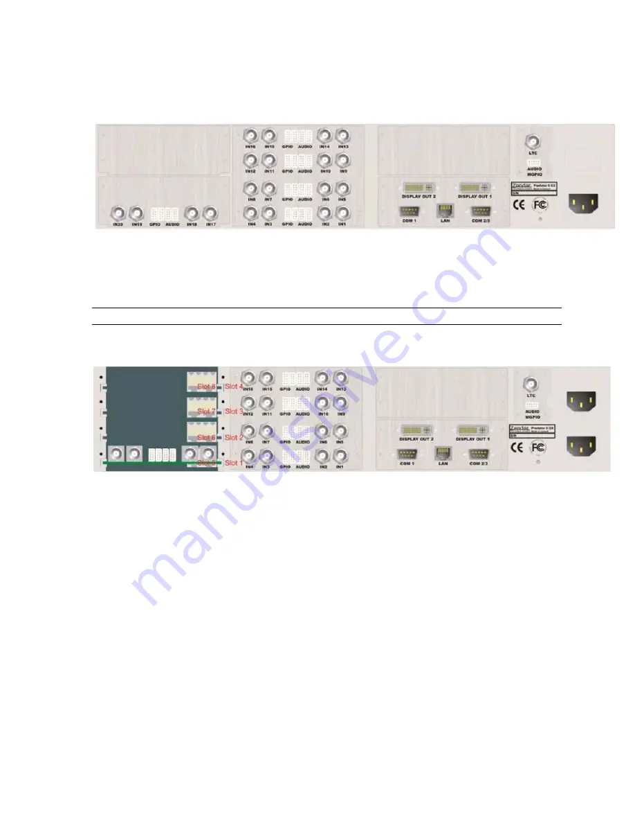
Figure 12:
Blank and partially populated panels removed ready to accept I/O cards
In the example above the first 16 video inputs use a 4-span VID4 panel and inputs 17 to 20 are fitted
to a partially populated 2-span video panel. Expansion might consist of (say) 12 more video inputs or
4 more video inputs and 4 DVI-I computer inputs.
This might be a good time to consider fitting a 2nd PSU if its not already installed.
3.
Remove as many blank or partially blank, panels as required, keeping the screws and blanks for
future use.
Figure 13:
Blank and partially populated panels removed ready to accept I/O cards
In the example above, the BNC nuts and serrated washers have been removed from inputs 17 to 20,
leaving the corresponding rear I/O card in place.
Fit the desired new rear I/O into available slots, ensuring that they fit securely into the rear of the
backplane.
Front loading processor cards and their I/O are normally fitted so that slots are populated with VID4
cards in low number slots starting at slot 1 and DVI-I cards in high slot numbers starting at slot 8.
Slot numbers are silk-screened on both sides of the backplane.


