Selenio
TM
VMG-14+ Hardware Setup Guide
50
Installation Instructions
Gen2 Release 1.4.0
Video
Processing
Module,
and
Transcoding
Modules
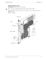
Slot Assignment
: VMG chassis-front, any slot in the range 3 to 14
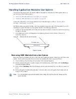
Use guidelines in
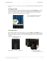
“Inserting VMG Modules—New System” on page 41
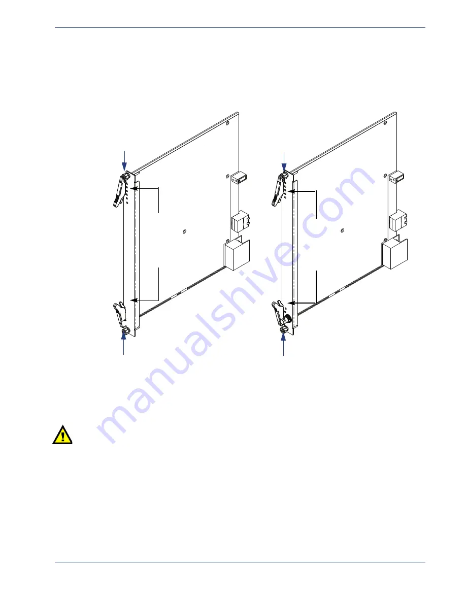
to place and secure the VPM
card(s) or TCM or TCM2 or TCM2+ cards (
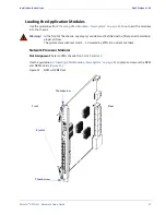
).
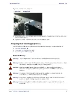
Figure 36.
VPM and TCM Cards
Double
‐
Checking
the
Physical
Installation
•
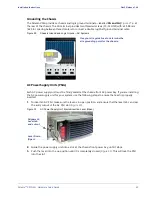
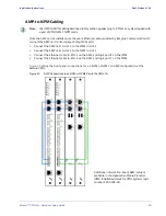
Ensure that all modules are firmly seated.
•
Ensure that the thumb screws for all modules are tightly secured.
Caution:
Ensure that Imagine Communications-supplied filler panels are installed in empty slots. This
is necessary to maintain proper airflow and prevent air from escaping out of the front of an
open slot.
Power
Up
and
Verify
1.
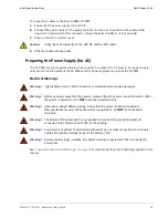
On a DC System, connect power to the PEMs.
On an AC System, set the circuit breaker of each AC PEM to be used to the ON position.
2.
Monitor the boot-up process, which proceeds as follows:
-
All of the LEDs on the SCM, the Fan Trays, the PEMs, the VPMs, the TCMs, and the NPMs
illuminate.
Ej
ec
to
r ha
nd
le
s
Eje
ct
or h
andl
es
VPM Card
TCM Card
Rear
Front
Front
Rear
Thumbscrew
Thumbscrew
Thumbscrew
Thumbscrew


