Selenio
TM
VMG-14+ Hardware Setup Guide
15
VMG-14+ Chassis and Components
Gen2 Release 1.4.0
Chassis
Front
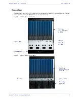
The VMG-14+ chassis cage front provides 14 vertical slots for loading of the application modules. Two
of these slots are dedicated for use by Network Processor Modules (NPM or NPM2) for 1:1 redundancy
configuration.
•
If the VMG-14+ is using GEN2 NPM2 cards, the remaining 12 slots can be used for Transcoding
Modules (TCM2, or TCM2+).
•
If the VMG-14+ is using GEN1 NPM cards, the remaining 12 slots can be used for Video Processor
Modules (VPM), Transcoding Modules (TCM), and up to two Application Media Processors (AMPs).
Note:
Rules for loading the various modules are applicable. See
“Basic Chassis Populations” on page 18
for more information.
System modules fit into numbered slots, from left (1) to right (14). Up to two Shelf Manager modules
fit into the two vertical slots at the left edge of the chassis, alongside slot 1. The AC (
) and DC
(
) VMG chassis are identical except for the inclusion of AC PSUs at the base of the AC chassis.
For slot assignments, see
Rack-mounting flanges are incorporated into the chassis at the left and right front edges, to enable
front-mount at the rack. During installation, you will prepare the rack by attaching a chassis shelf to it,
which will support the rear of the rack-mounted chassis.
Figure 4.
VMG-14+ Front—AC System
Power Bay: AC PSUs
Air Intake Grid
Fan Trays
Fan Filter Tray
Cable Management
Bracket
Card Cage:
Slots 1 through 14
ESD Jack
Shelf Control Modules
SCM 2
SCM 1
PSU 4
PSU 3
PSU 2
PSU 1


