background image


Controller

Section 6: Message Functions

Page 52 of 115

5760-121 Operations Manual Rev B

When the measurement has been determined,
it can be set in all bar code fields printed on the
substrate. The measurement is set by selecting
a bar code field, then the field type button fol-
lowed by the properties button. The factory
default setting is set for printing with V300 ink
on corrugate. 

Adding a label element:

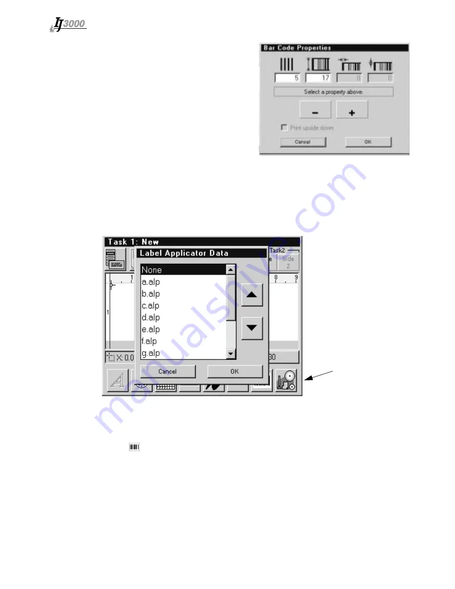
 When a print message with a bar code label element is loaded to

print, the IJ3000 instructs an attached Print and Apply Label Applicator to apply a label as
described by the attached .alp file. The attached file can be created using EasyLabel with
the "Print to file" feature and giving the file a .alp extension. The .alp file should then be
uploaded to the Controller (see 

Appendix E

).

To add a label element to the print message, touch the 

Label

 button. The Label Applicator

Data dialog is displayed. 

Select the file to be sent to the Label Applicator. 

Touch the 

OK

 button to close the dialog box and add the bar code label element to the

print message. Note that the Bar Code Label indicator is now displayed on the Edit
Screen. 

 Label Button

Summary of Contents for IJ300

Page 1: ...Operations Manual 1 Missouri Research Park Drive St Charles MO 63304 ServiceLine 1 800 526 2531 Illinois Tool Works Inc 2005 5760 121 Revision B Controller...

Page 2: ......

Page 3: ...ts publication Diagraph reserves the right to change or alter any information or technical specifications at any time and without notice 2005 Illinois Tool Works Inc All rights reserved Printed in the...

Page 4: ......

Page 5: ...nual Rev B The IJ3000 Controller including all components unless otherwise specified carries a limited warranty For all warranty terms and conditions contact Diagraph an ITW Company for a complete cop...

Page 6: ......

Page 7: ...ontrols 10 Buttons 10 Radio Buttons 11 Check Boxes 11 Value Entry Box 11 Text Entry Box 12 List Box 12 Message Selection Box 13 Inactive Controls 13 Keypad Controls 14 ESC Escape 14 Arrow Keys 14 Tab...

Page 8: ...ification URL 32 Setting IP Addresses 32 Defining User Codes 33 Time Date Screens 34 The Time Screen 34 The Date Screen 35 The Rollover Time Screen 36 Shifts 36 Auto Clean Setup for Impulse Jet Heads...

Page 9: ...atures 77 Power 77 CPU Board 78 Impulse Jet Print Head Interface Board 79 Integrated Valve Print Head Interface Board 80 Interconnect Diagrams 81 IJ3000 Controller CPU Diagram 81 Impulse Jet Controlle...

Page 10: ...0 101 Windows XP 101 Windows 2000 103 Windows 98 105 Windows 95 107 Appendix H Network Box 109 IJ3000 Network Box Menu Map 109 General 109 Main Menu 109 Task Menu 110 Purge Menu 110 Test Menu 110 Appe...

Page 11: ...asy to use soft ware The controller can be used as a stand alone device or networked through built in Ethernet connectivity The IJ3000 Controller can be configured for multiple print technologies incl...

Page 12: ...Controller Section 1 Introduction Page 2 of 115 5760 121 Operations Manual Rev B...

Page 13: ...ion CAUTION Turn off the equipment s main power before Performing preventive maintenance Performing any repairs to the unit Servicing the equipment in any manner ESD protection should be worn when ser...

Page 14: ...Controller Section 2 Safety Page 4 of 115 5760 121 Operations Manual Rev B...

Page 15: ...an IJ3000 Impulse Jet System 1 IJ3000 Controller 8 Encoder 2 CIDS3000 9 Ink Supply 3 Print Heads 10 Photo Sensor 4 Conveyor 11 Vacuum Waste Collector Bottle 5 Product 12 Encoder Cable 6 Print Head Br...

Page 16: ...ess Enclosure Dual Impulse Jet Interface European IJ3000 Controller Assemblies for Integrated Valve Systems 5760 001PV1D Painted Enclosure Single Integrated Valve Interface Domestic 5760 001PV2D Paint...

Page 17: ...dge of the product will reach the print head and at what rate of speed The controller comes in a stain less steel or painted metal case that makes it splash proof and resistant to electromagnetic inte...

Page 18: ...Controller Section 3 Typical System Components Page 8 of 115 5760 121 Operations Manual Rev B...

Page 19: ...on it Adjusting Screen Brightness The screen brightness control keys are at the top right corner of the keypad Press the up arrow key to make the screen lighter press the down arrow key to make the sc...

Page 20: ...ed with a box around them Inverse video example Press Press a keypad key to do or complete a particular action Examples Press Enter press ESC or press the Up Down arrows to scroll through the list of...

Page 21: ...ed value and press Enter Press ESC any time prior to pressing Enter to restore the original value Touching another screen control or pressing an arrow key after entering a new value but before pressin...

Page 22: ...t or right arrow keys to move the cursor to where text is to be added or removed then use the Backspace Delete key to remove unwanted text or type in additional text List Box Use a list box to select...

Page 23: ...the name in the box provided After a message is selected touch the screen button for the operation to be performed Inactive Controls When a screen control has no function within the context of the cu...

Page 24: ...shift to the next control in the general direction of the key pressed If no control lies in that direc tion input focus remains where it is When a text type screen control has input focus the left and...

Page 25: ...later in this Section Alt Alternate The Alt key is used in the Edit Screen to alter the action of the arrow and Enter keys See Editing a Message in Section 6 Message Functions F4 F8 The F4 F8 key pul...

Page 26: ...ead If printing on a single side of the product only one window is shown Two windows are displayed when utilizing two sided printing with the top window always being side 1 or the side closest to the...

Page 27: ...int Pause button to work When a task is empty no message is loaded to print its Print Pause button displays both an arrow and the double bars and is grayed out The Task 2 Print Pause button is not dis...

Page 28: ...nd dialog boxes input focus on the Edit Screen remains in one place the Edit Window Buttons outside of the Edit Window do function when touched but they can t be made to function from the keypad For i...

Page 29: ...down arrow up down 1 dot row 1 dot Alt up down arrow down Height of current font Height of current font Enter when no fields are highlighted and the crosshairs pointer is black left right 6 print colu...

Page 30: ...ght arrow left right 9 print columns Shift left right arrow left right 250 print columns Ctrl left right arrow left 1 print column Backspace Delete when no fields are highlighted left 9 print columns...

Page 31: ...hing the field directly Impulse Jet Integrated Valve Current Position Indicator The Current Position Indicator displays the current location of the crosshairs pointer selected field or edit cursor The...

Page 32: ...Controller Section 4 Getting Started Page 22 of 115 5760 121 Operations Manual Rev B...

Page 33: ...en prompts guide the user through the step by step print head setup procedure Once begun the procedure may be aborted by pressing Cancel or the Escape key at any time without changing the current prin...

Page 34: ...eyor The next screen will appear automatically Specifying Number of Print Heads Touch the up down arrows to set the number of print heads on each side of the conveyor The illustration at the top of th...

Page 35: ...is done the Print Head Proper ties screen appears NOTE The first print head in the daisy chain should be the top print head in the system as this one will be printing the top line of data and will be...

Page 36: ...uto cleaned or not Ink Type indicates the type of ink used for the selected print head For Integrated Valve The maximum sensor offset is 81 After a print head s properties are defined touch the Next H...

Page 37: ...olution cannot be changed it is fixed at 300 pulses per inch ppi for Impulse Jet and 100 ppi for Integrated Valve The Internal timer is used if the line speed is constant with a minimum of starts and...

Page 38: ...heads on each task The group function is only utilized for dual task control lers The system must be in group mode to create edit and print a group message NOTE Once a message is created or edited as...

Page 39: ...ncheck the Use task 1 CIDS check box to set the print heads on Task 2 to use the CIDS3000 connected to Task 2 CIDS3000 Detection Feature for Impulse Jet Only This feature will detect when a CIDS3000 i...

Page 40: ...m Setup screen 3 Touch the Serial Ports tab on the System Setup screen to display the Serial Ports page 4 Touch the COM1 or COM2 Function box to open a list box and select a device for the related por...

Page 41: ...xternal device on either serial port will work with messages printing on either task The serial port used must match the one specified when the message and vari able field are created see Variable Fie...

Page 42: ...controller boot up and at each photocell trigger input For more details see the Software Interface Document part number 5760 113 Setting IP Addresses Touch the IP Addresses tab to display the IP Addre...

Page 43: ...ng To display the Edit User Codes screen 1 On the Home Screen touch the Control Panels button to open the Control Panels Menu 2 Touch the User Codes button on the Control Panels Menu to open the Edit...

Page 44: ...g user codes avoid extremes in the number of characters for different codes within a component For example avoid defining hour 00 as A and hour 03 as AAAA If print codes like A and AAAA must be printe...

Page 45: ...he top left center of the screen is touched see below left To change the year touch the Year control at the top right center of the screen and select the year from the list displayed see above right N...

Page 46: ...en on the Time screen NOTE Rollover times between 12 00 PM and 11 59 PM will change the day date of auto codes before midnight rollover times between 12 00 AM and 11 59 AM will change the day date of...

Page 47: ...odic radio button to perform print head cleaning at set intervals and to dis play the controls for setting the interval period To set the maintenance interval 1 Touch the hour or minute control to hig...

Page 48: ...w buttons to set the minute the print heads are to be cleaned 6 Repeat until all cleaning times are programmed up to six per day NOTE To clean the print heads at the same time every day Monday through...

Page 49: ...90 C 194 F Use Sleep Mode to maintain the viability of the wax when the system is left on during long periods of printer inactivity eight to sixteen hours or longer To place a WaxJet task into sleep...

Page 50: ...on then touch the Wake Up button on the Print Menu Print is re enabled when the task s Print Heads and Wax Delivery System reach operating temperature Auto Sleep The IJ3000 can be programmed to automa...

Page 51: ...event 1 Set the day and time the system is to go to sleep a Touch the From Day box b Use the Up and Down Arrow buttons to set the day The large ones above the Enter button not the small ones in the D...

Page 52: ...e Print Menu on the Home screen 5 Sleep events are not tasks specific If your system is configured for two WaxJet tasks both tasks will enter and exit sleep mode at the programmed times To view or edi...

Page 53: ...lds may contain fixed text variable text a date code a time code or a product count Graphic fields contain either a logo or a bar code NOTE Please read Moving Around the Edit Screen in Section 4 Getti...

Page 54: ...d Product Setup Button Touch the Product Setup button to Set the product s length Set the print margins Set the print resolution dpi Select print options Status Indicators Displayed when Test Print is...

Page 55: ...add an incrementing or dec rementing product count or pallet count to a print message or to edit an existing count Variable Field Button Touch the Variable Field button to add a variable field to a pr...

Page 56: ...automatically copy to side 2 all fields entered on side 1 The Side 2 side 1 option is available only when both sides have the same number of vertical print dots Select Task 2 task 1 to automatically...

Page 57: ...yped It is also dis played in a box that appears at the bottom of the screen When finished press Enter The field s color changes to red If the field is not exactly where it should be use the arrow key...

Page 58: ...sert the time code into the print message If the time code is not exactly where it should be use the arrow keys to reposition it Press Enter when the time code is at the desired location Adding a prod...

Page 59: ...d dialog box is dis played Select the data source User The user is prompted to enter the data to be printed when the message is loaded to print Data 1 Data 10 Select Data 1 through Data 10 to use a co...

Page 60: ...n arrows to select a logo Touch the OK button to close the dialog box and insert the logo in the print message If the logo is not exactly where it should be use the arrow keys to reposition it Press E...

Page 61: ...or various substrates by printing a message that contains a Measure ink bleed bar code field Insert the bar code field by touching the bar code field button at the bottom of the Edit Screen then selec...

Page 62: ...print the IJ3000 instructs an attached Print and Apply Label Applicator to apply a label as described by the attached alp file The attached file can be created using EasyLabel with the Print to file...

Page 63: ...the message you wish to edit from the list or type the message name in the Message box 3 Touch the Edit button The Mes sages dialog box closes and the Edit Screen is displayed with the selected messag...

Page 64: ...n turns dark gray and the A on the button turns blue See the following examples Release a selected field by pressing the Enter key or by selecting another field Editing a Text Field 1 Select the field...

Page 65: ...Properties button the Field Properties dialog box is dis played 3 Change the field s properties as desired 4 Touch the OK button to close the dialog box and view the changes Touch the Cancel button to...

Page 66: ...OK button to close the Fonts dialog and view the change Touch the Cancel button to discard the change and close the dialog box 5 Press Enter to release the field its color changes from red to dark blu...

Page 67: ...The edit screen can be entered from either Task 1 or Task 2 Touch Side 1 under Task 1 and create the desired message Repeat for Side 2 under Task 1 and for Side 1 and 2 under Task 2 When this message...

Page 68: ...on Ink consumption is calculated by multi plying the average drop volume by the total number of dots in the printed message Side 2 Side 1 When the Side 2 Side 1 option is selected the total number of...

Page 69: ...d for printing a dialog box is displayed showing the current value of the count and allowing the operator to preset the count to any value within its defined limits For messages with two or more count...

Page 70: ...ts To adjust product counts for the current print message touch the Edit Counts button on the Home Screen The Product Counts dialog box is displayed The Total Count of All Products Printed is a non pr...

Page 71: ...nt dialog is a count internal to the pallet count It tracks the current number of items on the pallet When this count reaches the defined items per pallet the pallet count is incremented This Item Cou...

Page 72: ...Controller Section 6 Message Functions Page 62 of 115 5760 121 Operations Manual Rev B...

Page 73: ...nt print message or check system status NOTE Password protection prevents the Print Messages Control Panels and Time Date buttons on the Home Screen from being displayed when the Show Menu button is t...

Page 74: ...otocell is not blocked Indicates the task photocell is blocked Indicates the task print buffer is empty or print is paused Indicates a print message is in the print buffer and print is enabled not pau...

Page 75: ...the task s daisy chain have an empty ink reservoir Printing stops Indicates the ink waste bottle on the CIDS3000 is less than full and the ink pump is supply ing sufficient ink to the print heads Ind...

Page 76: ...daisy chain are at operating temperature 115 C 239 F Indicates the task is in Sleep Mode wax temperature is 90 C 194 F Indicates one or more print heads or Wax Delivery Systems in the task s daisy cha...

Page 77: ...the Wax Delivery Systems in the daisy chain Look at the LOW INK LED on the back of the Wax Delivery Systems to identify which system needs wax A Low Wax condi tion automatically changes to Wax Out in...

Page 78: ...wo seconds Ink Level Status Ink Line Status Memory Usage displays the percent age of available flash and RAM that is currently being used A green yellow red indicator under the flash usage bar advises...

Page 79: ...en is so far out of calibration that it is inoperable you will have to call up the calibration utility using the keyboard From the Home Screen press the space bar to dis play the Home Screen menu the...

Page 80: ...nges Extended characters that are not on the standard keyboard may be used for File Names Shift Codes User Codes and Variable Field names To use extended characters select the message or field to be c...

Page 81: ...eboot Should the system ever become unresponsive or display an Out of memory message a system reboot must be performed Press and hold CTRL and ALT then press the ON but ton CAUTION Any message that wa...

Page 82: ...Controller Section 7 Utility Functions Page 72 of 115 5760 121 Operations Manual Rev B...

Page 83: ...res built into the system Troubleshooting Notes Controller Most controller problems will be the result of improperly connected cables Check all con nections including power interface print heads encod...

Page 84: ...onse from keypad entry Keypad Assembly Inspect flex cable for damage particularly at end going into CPU connector System not printing Interface Board Test Interface Board Test Points See Appendix B fo...

Page 85: ...15 24 30 48 63 96 and 126 standard and bold for IJ384 and IJ768 Head Integrated Valve 5 dot 7 dot 9 dot 18 dot Storage 2 meg flash memory is available for message files and logo files Print Speed Up t...

Page 86: ...endix C Electrical 90 260 VAC 50 60 Hz 3 0A max power supply input Impulse Jet 24 VDC 5 0A per interface card controller input Integrated Valve 15VDC 4 6A per interface card controller input Environme...

Page 87: ...power from the print heads and photosensor if the voltage is less than 18V On Integrated Valve systems an over voltage circuit de energizes K1 and removes power from the print heads and photosensor if...

Page 88: ...ay RAM The real time clock and calendar U2 keep system time The 3V battery BT1 preserves system data and keeps the clock running during power outages or when the IJ3000 is not plugged into a power out...

Page 89: ...ATA CLOCK and LATCH take place in the FPGA in response to signals from the photosensor and encoder Test Points TP1 5VDC TP2 3 3VDC TP3 2 5VDC TP4 GND TP5 FPGA PROGRAM pulses low to initiate FPGA progr...

Page 90: ...d and circuitry on the FPGA reads the print image and shifts it out to the print heads The generation and timing of all daisy chain signals DATA CLOCK and LATCH take place in the FPGA in response to s...

Page 91: ...Controller Appendix B Theory of Operation 5760 121 Operations Manual Rev B Page 81 of 115 Interconnect Diagrams IJ3000 Controller CPU Diagram...

Page 92: ...INKLOW ATEMP GND 24V GND GND IDS_ERROR LATCH LATCH DATA3 DATA3 24V DATA4 CLOCK CLOCK DATA DATA2 DATA2 DATA GND GND XIDS_ERROR XINKOUT 3 XINKLOW XPUMP 1 2 XVACUUM 6 5 4 V N C 8 7 GND XVACUUM XPUMP XINK...

Page 93: ...2 11 3 4 10 6 7 13 14 15 CLOCK DATA LATCH LATCH DATA CLOCK N C 10 2 1 9 4 11 3 GND N C N C GND 15V GND 15V 6 5 13 12 15 14 7 15V 8 8 CLOCK CLOCK DATA LATCH DATA LATCH N C 15V GND GND N C N C GND 15V 1...

Page 94: ...Controller Appendix B Theory of Operation Page 84 of 115 5760 121 Operations Manual Rev B...

Page 95: ...ructions ATTENTION Il y a danger d explosion s il y a remplacement incorrect de la batterie Rem placer uniquement avec une batterie du m me type ou d un type quivalent recommand par le constructeur Me...

Page 96: ...Controller Appendix C Parts and Supplies Page 86 of 115 5760 121 Operations Manual Rev B...

Page 97: ...Task2 are printing this same message the sum of the maximum field stacks of Task1 and Task2 is ten fields Thus the maximum field stack the controller has to process is ten fields Task1 Task2 5 5 10 f...

Page 98: ...higher the density the higher the ink flow demand is in the print head A typical alpha numeric message has a print density of about 20 while a 100 magnification I 2 of 5 bar code has a print density o...

Page 99: ...s setting is measured in dots per inch a setting of 4 denotes 4 dots or print col umns per inch Resolution can be set from 4 to 25 dpi 2 The operating frequency of the solenoids can be determined with...

Page 100: ...Controller Appendix D Performance Parameters Page 90 of 115 5760 121 Operations Manual Rev B...

Page 101: ...760 121 Operations Manual Rev B Page 91 of 115 Appendix E Creating Transferring Logo Files Creating a Logo Open Paint from a PC by selecting Start Programs Accessories and then Paint Bring up the Attr...

Page 102: ...115 5760 121 Operations Manual Rev B Enter the Width and Height of the logo in Pixels then select Black and white Choose Yes at the screen prompt to convert to black and white Zoom in by selecting Vie...

Page 103: ...ogo Files 5760 121 Operations Manual Rev B Page 93 of 115 Define the pixels of the logo by using the pencil tool Bring up the Flip and Rotate dialog by selecting Image Flip Rotate Select Rotate by ang...

Page 104: ...Controller Appendix E Creating Transferring Logo Files Page 94 of 115 5760 121 Operations Manual Rev B Name the logo and save it as a Monochrome Bitmap file in the desired folder...

Page 105: ...te with the IJ3000 1 Obtain the IJ3000 controller s IP address Most IJ3000 controllers have an IP address of 10 1 2 3 It may be different if the controller is networked with other IJ3000s or other dev...

Page 106: ...button to locate and select the file to be sent to the controller 6 Click Upload to send the file to the controller If the file transfer is successful the web page shown below will be displayed If the...

Page 107: ...have an IP address of 10 1 2 3 It may be different if the controller is networked with other IJ3000s or other devices If the IP address is unknown go to the controller and from the Home Screen Touch t...

Page 108: ...be transferred to the IJ3000 Click on the file name to display the Windows File Download dialog box 6 Click OK A standard Windows Save As dialog box is displayed 7 Navigate to the desired folder and c...

Page 109: ...number 5760 240 shipped with the IDS3000 The setip exe program Available from Diagraph Customer Service Phillips head screwdriver Procedure 1 Install the setip exe program on your PC 2 Unplug the IDS...

Page 110: ...d setip exe 8 Type setip followed by a space followed by the IDS3000 MAC address recorded in step 4 followed by a space followed by the IP address for the IDS3000 then press Enter For example type set...

Page 111: ...IJ3000 This appendix has instructions for setting the IP address and subnet mask of the PC so it can communicate with the IJ3000 Controller Included are instructions for Windows XP Windows 2000 Windo...

Page 112: ...IJ3000 Page 102 of 115 5760 121 Operations Manual Rev B 3 Select Internet Protocol TCP IP then click the Properties button 4 Click the Use the following IP address radio button Enter an IP address of...

Page 113: ...Communicate with the IJ3000 5760 121 Operations Manual Rev B Page 103 of 115 Windows 2000 1 Open the Start menu select Settings then Network and Dial up Connections 2 Click the desired connection then...

Page 114: ...J3000 Page 104 of 115 5760 121 Operations Manual Rev B 3 Select Internet Protocol TCIP IP then click the Properties button 4 Click the Use the following IP address radio button Enter an IP address of...

Page 115: ...to Communicate with the IJ3000 5760 121 Operations Manual Rev B Page 105 of 115 Windows 98 1 Open the Start menu select Set tings then Control Panel 2 Double click the Network icon bottom row second f...

Page 116: ...IJ3000 Page 106 of 115 5760 121 Operations Manual Rev B 3 Select TCP IP and click the Properties button 4 On the IP Address page click the Specify an IP address radio button Enter an IP address of 10...

Page 117: ...ring a PC to Communicate with the IJ3000 5760 121 Operations Manual Rev B Page 107 of 115 Windows 95 1 Open the Start menu select Set tings then Control Panel 2 Double click the Network icon lower rig...

Page 118: ...IJ3000 Page 108 of 115 5760 121 Operations Manual Rev B 3 Select TCP IP then click the Properties button 4 On the IP Address page click the Specify an IP address radio button Enter an IP address of 1...

Page 119: ...ow a single arrow for Task 1 operations and a double arrow for Task 2 operations Press the Enter key to perform the function or display the sub menu Select Exit on a menu and press Enter to return to...

Page 120: ...hrough Purge Head 8 is displayed Select a print head and press Enter The print head will purge for about 3 seconds Printing must be paused to purge a print head Press Enter again to stop purging befor...

Page 121: ...e entire installation but not the branch circuits individu ally At the service equipment a single ground wire connects both the neutral and ground to earth The NEC calls this wire the ground electrode...

Page 122: ...Controller Appendix I Testing an Electrical Outlet Page 112 of 115 5760 121 Operations Manual Rev B...

Page 123: ...charged to an electronic circuit components or printed circuit boards permanent damage may also occur This damage may be in the form of reduced functionality reduced life or complete non function alit...

Page 124: ...Controller Appendix J Electrostatic Discharge ESD Page 114 of 115 5760 121 Operations Manual Rev B...

Page 125: ...put Focus A screen control that receives input by information entered through the key pad Inverse Video Information on the computer screen in which the typeface is light and the background is dark As...

Reviews: