


8
Preparations
• Setting up:
- Place the unit on an even, stable, clean, nonslip, dry
and fireproof surface�
- Keep at least 20 cm of open space on the front and rear
side�
- The place for installation should be large enough and
provide sufficient air ventilation to ensure the room
does not warm up excessively because of the heat
from device radiates to the environment�
- Do not set up the device in the immediate vicinity of
heat sources and do not expose to sun light�
- Cooling machine, pump motor and electronics produce
intrinsic heat that is dissipated via the venting grids (3)!
Never cover these venting grids!
Note:
After setting up the device, wait at least one hour be-
fore starting the operation to avoid the damage to the cool-
ing system�
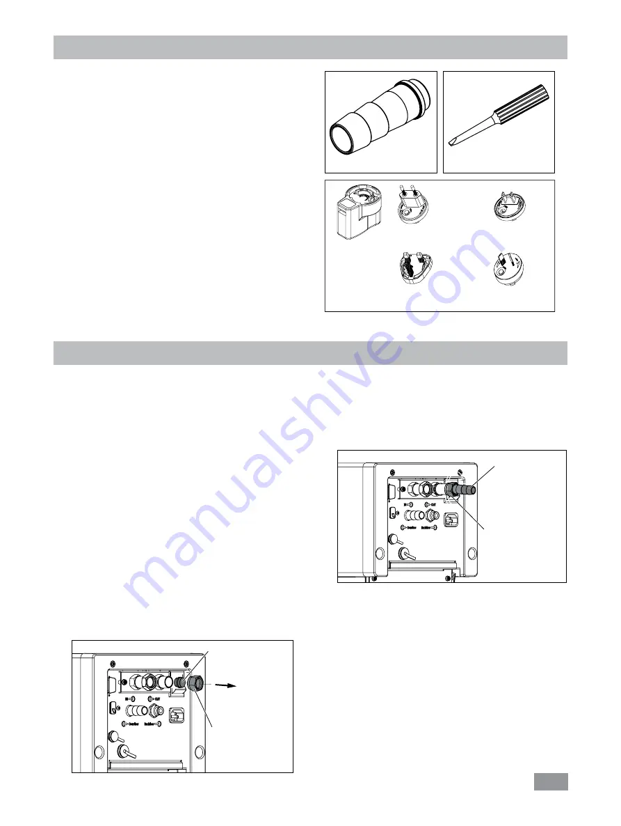
• Connecting the tubings:
- Unscrew the union nuts and stoppers using a wrench
(SW19) from the pump connector
IN
(14) and
OUT
(13)�
- Connect the hoses for circulating the external system to
the pump connection M 16 x 1 for
IN
and
OUT
directly
or with the olives�
- Screw the hose olives to the pump connection IN and
OUT with union nuts� Slide the hoses (NW 12) onto the
olives� The hoses must be secured with suitable clamps�
Unpacking
• Unpacking:
- Unpack the device carefully�
- Any damage should be notified immediately to the
shipping agent (post office, railway network or logistics
company)�
• Delivery scope:
-
HRC 2 control
with
WiCo
- Power cables
- Hose olive NW 8 (2 pieces)
see Fig� 2
- Hose olive NW 12 (2 pieces)
see Fig� 2
- Screwdriver (use for safety circuit)
see Fig� 3
- OS 1�0 power supply (for
WiCo
)
see Fig� 4
- USB 2�0 cable micro A–micro B
- USB 2�0 cabel A–micro B
- Plastic cap (for “
Overflow
” connector)
- Plastic cap (for “
Backflow
” connector)
- User guide
- Warranty card�
Adapter
England
Adapter
Australia
Adapter
Europe, Switzerland
Fig. 4
Adapter
USA, China
Fig. 3
Fig. 2
- Via a hose to the “
Overflow
” connector, overflowing
fluid can be directed into a suitable vessel� The vessel
should be positioned lower than the “
Overflow
” con-
nector�
- Connect the “
Backflow
” connector to
IKA
®
calorim-
eter with a suitable hose�
Fig. 5
Union nut
Stopper
Fig. 6
Union nut
Olive
Fig. 5


