11
UK
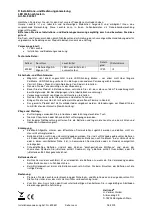
fig. 5-3
fig. 5-4
SP
rP
t
L
FH
FL
1
0
1
0
FE
Fno
Fnc
L :
HY:
FE:
Level
Hysteresis
Window
• For the switching output a switch-off delay of max. 60 s can be set (e.g. for
especially long pump cycles).
6.2.4 Damping function
With unsteady level (e.g. turbulence, wave movements...) display and output
response may be damped. During damping the determined level values are
"smoothed" by means of a mean filter; the result is a steady curve. The damping
constant Τ*
)
*
)
Τ indicates after what time 63 % of the final value are reached in the event of a sudden
jump. After 5 T almost 100 % have been reached.
6.2.5 Defined state in case of a fault
• In case of a fault a state can be defined for each output.
• If a fault is detected or if the signal quality is below a minimum value, the
outputs pass into a defined state according to NAMUR recommendation
(NE43). For this case the response of the outputs can be set via the
parameters [FOU1], [FOU2]
• Temporary loss of signal caused e.g. by turbulence or foam formation can be
[dFo]). During the delay time the last
measured value is frozen. If the measured signal is received again in sufficient
strength within the delay time, the unit continues to work in normal operation. If,
however, it is not received again in sufficient strength within the delay time, the
outputs pass into the defined state.