background image

Parameterisation connection

Connect the USB adapter cable E2D100 to the parameterisation connection of the
sensor. Ensure for connection of the M8 connector that the coupling nut is tightly
screwed into the internal thread of the sensor socket.

Only connect the USB connector of the adapter cable E2D100 with your PC
after installation of the software!

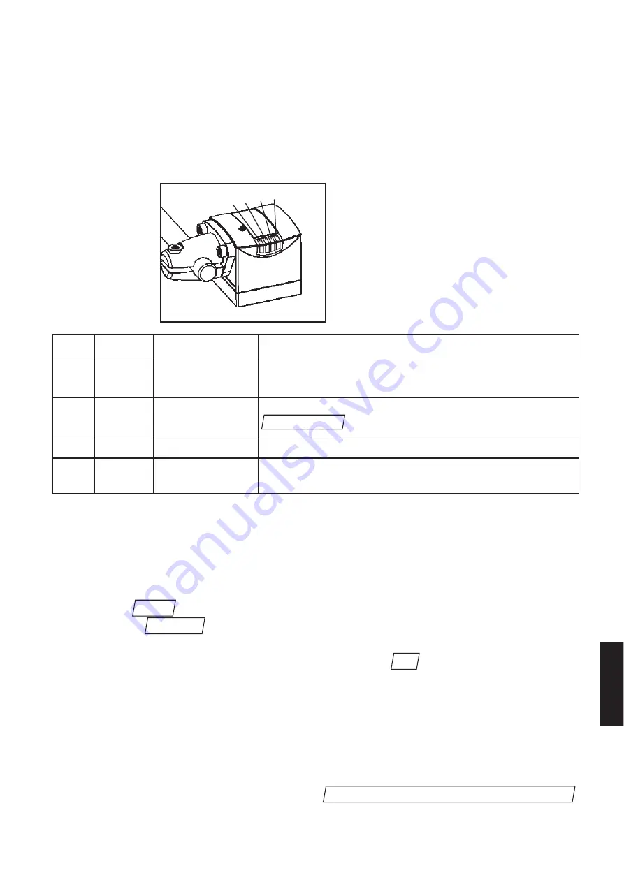
LED display

LED no.  Colour 

Type of indication  Function

1

LED green

flashing

operating voltage applied - sensor parameters not yet set; 

permanently lit

data set has been loaded - sensor's parameters set and ready

2

LED yellow

permanently lit

communication with the PC is active (USB connection exists 

menu item executed)

3

LED yellow

permanently lit

contour has been detected - switching output switched

4

LED red

permanently lit

error message: contour has not been detected 
output has not been switched

Software installation

Insert the CD with the dualis control panel operating program (E2D102) into your CD
drive. If the installation does not start automatically, use the following commands to
start it manually:

• Select the 

command in the start menu. A dialogue window will open.

• Activate the 

button and change to the  English directory on the CD ROM

in the selection window.

• Open the 

setup.exe

file and confirm the selection by 

.

The installation will start. 

Follow the instructions of the installation program.

After successful installation connect the USB connector of the adapter cable E2D100
to your PC. This will start automatic hardware recognition of your operating system.
Follow the instructions of the hardware wizard and during the query for the process
for the driver selection select the option 

.

Browse searching for the driver of the unit. 

OK

Browse... 

Run... 

connect sensor 

23

ENGLISH

1 2 3

4

Summary of Contents for efector 250

Page 1: ...Bedienungsanleitung Operating instructions Notice pour utilisateurs Kontursensor Contour sensor Capteur de contours Sachnr 701843 00 07 04 DEUTSCH ENGLISH FRANÇAIS ...

Page 2: ...Sensors 5 Konfigurationsdateien verwalten 6 Bildqualität einstellen 8 Bildaufnahmebereichs und Empfindlichkeitseinstellung 9 Beobachtungsbereiche und beobachtete Konturen 10 Toleranzfestlegung und Test der Toleranzschwellen 11 Trigger konfigurieren 14 Gesamttest durchführen 16 Sensor beobachten 17 Service Modus 17 Anhang 19 Funktion der Schalteingänge 19 Funktion der Schaltausgänge 20 Anschlussbel...

Page 3: ...Elektrofachkraft installiert werden Schalten Sie die Anlage vor dem elektrischen Anschluss spannungsfrei Prozessanschluss Schließen Sie die Versorgungsspannung von 24 V DC entsprechend der im Anhang Seite 20 angegebenen Belegung des M12 Prozessanschlusses an Info Beim erstmaligen Einschalten des Sensors blinkt die grüne LED für die Betriebsbereitschaftsan zeige Dies zeigt an dass noch keine gültig...

Page 4: ...4 LED rot dauerhaft Fehlermeldung Kontur wurde nicht erkannt Schaltausgang wurde nicht geschaltet Installation der Software Legen Sie die CD mit dem Bedienprogramm dualis Control Panel E2D102 in Ihr CD Laufwerk Sollte die Installation nicht automatisch starten so muss die Installation manuell gestartet werden Wählen Sie im Startmenü den Eintrag Ein Dialogfenster wird geöffnet Betätigen Sie die Sch...

Page 5: ...e Nach erfolgreicher Verbindungsauf nahme wechselt in der Statuszeile die Anzeige von OFFLINE auf ONLINE und die gel be Verbindungsstatusanzeige am Sensor leuchtet auf Die Auswahl der Schnittstelle kann auch über den Menüpunkt im Menü erfolgen Eine Verbindung über die zuletzt ausgewählte Schnittstelle wird hergestellt wenn Sie den Menüpunkt im Menü wählen Die Einstellung der Sprache des Bedienprog...

Page 6: ... siehe Anhang Seite 19 Über die Schaltflächen stehen folgende Möglichkeiten für eine Konfigurationsdatei zur Verfügung Erstellen einer neuen Konfigurationsdatei Selektieren Sie einen freien Listenplatz und betätigen Sie die Schaltfläche Es öffnet sich ein Dialog in dem Sie den Namen der neuen Konfigurationsdatei eingeben können Anschließend gelangen Sie zur Dialogseite Seite 8 Aktivieren einer bes...

Page 7: ...bgelegt Löschen einer bestehenden Konfigurationsdatei Die selektierte Konfigurationsdatei wird gelöscht Sicherheitshalber wird über einen Dialog abgefragt ob Sie die Konfigurationsdatei wirklich löschen möchten Konfiguration laden Wenn Sie einen freien Listenplatz selektiert haben können Sie eine auf Ihrem PC gespeicherte Konfigurationsdatei auf den Sensor laden Der Name unter dem die Konfiguratio...

Page 8: ...lag für die optimale Bildhelligkeit In der Regel werden Sie mit einer externen Beleuchtung arbeiten Sollten Sie dennoch mit der internen Beleuchtung des Sensors arbeiten so können Sie diese über den Aus wahlschalter aktivieren Info Beim Bearbeiten eines bestehenden Parametersatzes wird zunächst das gespeicherte Refe renzbild für diesen Parametersatz angezeigt Über die Schaltfläche können Sie den L...

Page 9: ...welle stellen Sie mit dem Schieberegler ein Alle Grauwerte unterhalb des Schwellwer tes werden als Schwarz klassifiziert alle Werte über dem Schwellwert als Weiß Über die Schaltfläche schlägt der Sensor automatisch einen optimalen Wert für die Binarisierungsschwelle vor Zum Test der Einstellungen mit verschiedenen Mustern können Sie durch Betätigen der Schaltfläche die Bildanzeige aktualisieren De...

Page 10: ...ch tungsbereiches werden farblich hervorgehoben Einen Rahmen für einen weiteren Beobachtungsbereich können Sie erzeugen indem Sie die Schaltfläche betätigen und dann mit der Maus den neuen Rahmen aufziehen Bitte beachten Sie dabei folgendes Beobachtungsbereiche dürfen sich nicht überschneiden Beobachtungsbereiche innerhalb anderer Beobachtungsbereiche sind unzulässig Es können maximal 8 Beobachtun...

Page 11: ...ssig sind Selektieren Sie zunächst mit einem Doppelklick die Konturen die Sie bearbeiten möchten Die selektierten Konturen werden in der Farbe rot dargestellt Nicht selek tierte Konturen werden in der Farbe gelb dargestellt Hinweis Durch Doppelklick auf den Rahmen eines Beobachtungsbereiches können Sie alle Konturen innerhalb des Bereiches auf einmal selektieren Über das Auswahlfeld können Sie dan...

Page 12: ...iel Prozent der Bildpunkte bezogen auf die Gesamtlänge der Kontur außerhalb des Toleranz schlauches liegen dürfen damit die detektierte Kontur bei der Auswertung noch als gut bewertet wird Liegen mehr Bildpunkte außerhalb der Kontur so wird diese als schlecht bewertet Zum Test der getroffenen Einstellungen können Sie im Auswahlfeld die Ein stellung wählen und dann Ihre Prüfmuster vor dem Sensor po...

Page 13: ...h ist erscheint im Anzeigefeld die Meldung Fehler mindestens eine Kontur nicht passend In diesem Fall wird die Ist Kontur nicht angezeigt und das Prüfteil wird als Schlechtteil klassifi ziert Die Anzeige gibt die Anzahl der Fehlerpixel bezogen auf die maximal erlaubte Zahl von Fehlerpixeln an Info Wenn Sie für eine Kontur mit einer Länge von 100 Punkten einen Fehler von 10 eingestellt haben dann s...

Page 14: ...i der internen Triggerung können Sie eine horizontal oder vertikal orientiertes Bild fenster den sogenannten Triggerbalken definieren Die Orientierung wird über das Auswahlfeld festgelegt Position und Größe des Triggerbalkens lassen sich mit der Maus ändern Info Im Vergleich zur horizontalen Triggerorientierung weist die vertikale Triggerorientierung eine deutlich höhere Reaktionszeit auf Es empfi...

Page 15: ...eeinflussen Durch Betätigen der Schaltfläche wird die Triggerschwelle anhand des Trig gerbalkens automatisch ermittelt Mit der Schaltfläche wird ein neues Bild aufgenommen und dargestellt Zum Test der Triggereinstellungen können sie den einstellen Im Modus wird das Sensorbild fortlaufend aktualisiert Im Modus wartet der Sensor auf ein Trigger Ereignis und zeigt den aktuellen Status im Meldungsfens...

Page 16: ...be LED für IO bzw eine rote LED für NIO signalisiert Für die Positionierung anderer Testmuster können Sie den Modus wählen Das Bild wird dann fortlaufend aktualisiert eine Aus wertung findet nicht statt Betätigen Sie nach Abschluss des Gesamttests die Schaltfläche Sie wer den dann über ein Dialogfenster gefragt ob der erstellte oder bearbeitete Datensatz abgespeichert werden soll Anschließend gela...

Page 17: ... Der Service Modus arbeitet ähnlich wie der Monitormodus zusätzlich wird jedoch das vom Sensor aufgenommene Bild angezeigt Info Im Service Modus ist die Auswerterate deshalb nochmals geringer als im Monitor Modus Über die Schaltfläche werden alle relevanten Informationen der akti ven Konfigurationsdatei das Referenzbild die Konturschläuche das aktuelle Bild und falls vorhanden das Bild der letzten...

Page 18: ...gen zurückgesetzt werden Info Bilder werden im gleichen Verzeichnis wie der Servicebericht gespeichert Durch Betätigen der Schaltfläche gelangen Sie vom Service Modus zurück in den Monitormodus Über die Schaltfläche wechseln Sie in die Dialog seite Konfigurationsdateien verwalten Parameter Monitor Statistik zurücksetzen 18 ...

Page 19: ...der Trigger Sperrzeit der Ausgang READY ausgeschaltet und erst nach Ablauf der Sperr zeit wieder eingeschaltet Die Trigger Sperrzeit beträgt max 1 s wenn keine Verbindung zwischen Bedienpro gramm und Sensor aufgebaut ist und sie beträgt max 3 s wenn das Bedienpro gramm mit dem Sensor verbunden ist Das nachstehende Diagramm veranschaulicht diesen Zusammenhang Programmwahl Konfigurationsdateien verw...

Page 20: ...enn nach der Auswertezeit tA der READY Ausgang geschaltet wird ist die Auswertung beendet und das Ergebnis kann am Anschluss OUT abgefragt werden Das nachstehende Diagramm verdeutlicht die Zusammenhänge Anschlussbelegungen 20 IO NIO tA tA Prozessanschluß M12 8 polig 1 U 2 Triggereingang 3 0V 4 Triggerausgang für externe Beleuchtung 5 Schaltausgang READY 6 Schaltausgang OUT 7 Schalteingang IN0 8 Sc...

Page 21: ...setting of the sensor 24 Manage configuration data 25 Set image quality 27 Image zone and sensitivity setting 28 Search zones and monitored contours 29 Definition of tolerances and test of the tolerance thresholds 30 Configure trigger 33 Perform overall function test 35 Monitor sensor 36 Service mode 36 Annex 38 Function of the switching inputs 38 Function of the switching outputs 39 Wiring 39 21 ...

Page 22: ...nnected by a qualified electrician Disconnect power before connecting the unit Process connection Connect the supply voltage of 24 V DC according to the wiring diagram of the M12 process connection indicated in the annex page 39 Info When the sensor is switched on for the first time the green LED for indicating readiness for operation flashes This shows that no valid configuration file has been st...

Page 23: ...ly lit error message contour has not been detected output has not been switched Software installation Insert the CD with the dualis control panel operating program E2D102 into your CD drive If the installation does not start automatically use the following commands to start it manually Select the command in the start menu A dialogue window will open Activate the button and change to the English di...

Page 24: ...m OFFLINE to ONLINE and the yellow connection status display on the sensor will light The port can also be connected via the menu item in the menu A connection via the port selected last is established when you select the menu item in the menu The setting of the language of the operating program and the path for the file stor age can be changed via the and menu items in the menu if there is no con...

Page 25: ...ion data file are available via the buttons Create a new configuration data file Select a free list place and activate the button A dialogue will open into which you can enter the name of the new configuration data file Then con tinue to the dialogue page page 27 Activate an existing configuration data file With this button you determine the selected configuration data file as active set ting Afte...

Page 26: ...ta file The selected configuration data file will be deleted To be on the safe side you will be asked via a dialogue if you really want to delete the configuration data file Load configuration When you have selected a free list place you can load a configuration data file stored on your PC into the sensor The name under which the configuration data file is to be stored in the sensor can be entered...

Page 27: ...suggestion for the optimum image brightness You will usually work with an external lighting If you need to use the internal light ing of the sensor you can activate it by means of the selector switch Info When editing an existing parameter set first the stored reference image for this parameter set is shown You can activate the live image mode via the button Continue to the next step of parameter ...

Page 28: ...ack and white image by means of the slider bar All grey scale values below the threshold value are classified as black all values above the threshold value are classi fied as white Via the button the sensor automatically suggests an optimum value for the binarisation threshold You can update the image by activating the button to test the settings with different samples The sensor shows all contour...

Page 29: ...an generate a frame for another search zone by activating button and then create a new frame by means of the mouse Please note the following The search zones must not overlap Search zones within other search zones are not permissible A maximum of 8 search zones can be defined To process an existing search zone you first have to select it by double clicking on the frame Then you can modify its size...

Page 30: ...the frame of the search zone You can then define via the field if the selected contours are to be taken into account for the evaluation or not selection or Con tours which have not been taken into account are shown in blue If a contour which has not been taken into account is selected by means of a double click the colour changes to purple The zone in which the detected contour is to be located is...

Page 31: ...s carry out the evaluation for the respective test piece Info If possible select the test pieces in such a way that the range of the part tolerances occurring in the process is covered as much as possible As a result the contour bands are shown together with the detected actual contours The image pixels of an actual contour positioned within the contour band are shown in light blue The image pixel...

Page 32: ...or pixels referred to the maximum permissible number of error pixels Info If you have set an error of 10 for a contour with a length of 100 pixels a maximum of 10 error pixels outside the contour band are allowed In case of 5 error pixels the contour match is 50 with 10 error pixels it is 0 and with 0 error pixels the match is 100 Depending on the evaluation results you can optimise the settings i...

Page 33: ...ly or vertically oriented image field the so called trigger bar The orientation is defined via the selection field Position and size of the trigger bar can be modified by means of the mouse Info Compared to the horizontal trigger orientation the vertical trigger orientation has a consider ably longer response time It is recommended to turn the sensor by 90 if necessary The value of the slider bar ...

Page 34: ...ctivating the button the trigger level is auto matically defined by means of the trigger bar Via the button a new image is captured and shown To test the trigger settings you can set the In the mode the sensor image is continuously updated In the mode the sensor waits for a trigger result and shows the current status in the display window To do this the percentage of dark and light image pixels in...

Page 35: ... position other test samples you can select the mode The image will be updated continuously there will be no evaluation After completion of the overall test activate the button Then you will be asked via a dialogue window if the parameter set which has been created or edited is to be stored Then continue to the dialogue page The newly created or edited and stored parameter set was automatically ac...

Page 36: ... is shown Info In the service mode the evaluation rate is therefore even slower than in the monitor mode Via the button all relevant information of the active configuration data file the reference image the contour bands the current image and if any the image of the last FAIL evaluation are stored on the PC in the report file cs_report html You can select and open the service report e g via the me...

Page 37: ...the same directory as the service report By activating the button you will return from the service mode to the mon itor mode You will change to the dialogue page via the button Parameter Manage configuration data Monitor 37 ENGLISH ...

Page 38: ...DY is switched off during the trigger disable time and only switched on again when the dis able time has elapsed The trigger disable time is max 1 s if no connection between the operating program and the sensor has been established and it is max 3 s if the operating program is con nected with the sensor The following diagram illustrates this correlation Program selection Manage configuration data ...

Page 39: ...shed if the READY output is switched after the evaluation time tE has elapsed and the result is available at the connection OUT The following diagram illustrates the correlation Wiring 39 ENGLISH IO NIO tA tA Process connection M12 8 pole 1 U 2 trigger input 3 0V 4 trigger output for external lighting 5 switching output READY 6 switching output OUT 7 switching input IN0 8 switching input IN1 Param...

Page 40: ...3 Paramétrage du capteur 43 Gestion des paramétrages 44 Réglage de la qualité de l imagen 46 Zone image et réglage de sensibilité 47 Définition de la zone de recherche et du contour 48 Définition des tolérances et test 49 Configuration du trigger 52 Fonction test complet 54 Mode détection 55 Mode service 55 Annexe 57 Fonction des entrées de commutation 57 Fonction des sorties de commutation 58 Bra...

Page 41: ...rique L appareil doit être monté par un électricien qualifié Mettez l installation hors tension avant de raccorder l appareil Connexion process Raccordez l alimentation de 24 V DC selon le branchement de la connexion process M12 indiquée en annexe page 58 Info Lors de la première mise sous tension du capteur la LED verte indiquant la disponibilité clignote Ceci indique qu un paramétrage valable n ...

Page 42: ...sage d erreur Contour non détecté Sortie non commutée Installation du logiciel Insérez le CD contenant le progiciel dualis Control Panel E2D102 dans le lecteur CD Si l installation ne démarre pas automatiquement elle doit être démarrée manuelle ment Dans le menu de démarrage sélectionnez Une fenêtre de dialogue est ouverte Cliquez sur le bouton et passez dans le répertoire Français sur le CD ROM d...

Page 43: ...ans la ligne d état et la LED jaune du capteur indiquant l état de connexion est allumée Ensuite l interface peut être sélectionnée par le point dans le menu Une connexion via l interface sélectionnée la dernière est établie lorsque vous sélec tionnez le point dans le menu La sélection de la langue du progiciel utilisateur et du chemin pour le stockage de fichiers peut être modifiée par les points...

Page 44: ... être sélectionnées avec les boutons correspondants Créer un nouveau paramétrage Sélectionnez une place libre dans la liste et cliquez sur le bouton Une fenêt re de dialogue s ouvre dans laquelle vous pouvez saisir le nom du nouveau paramé trage Ensuite vous passez à la page de dialogue page 46 Activer un paramétrage existant Le paramétrage sélectionné est activé Après la mise sous tension du capt...

Page 45: ...e fenêtre de dialogue vous demande si vous êtes sûr d effacer le paramétrage Charger un paramétrage Si vous avez sélectionné une place libre dans la liste vous pouvez charger un paramétrage stocké sur votre PC dans le capteur Le nom sous lequel le paramé trage doit être mémorisé dans le capteur peut être saisi dans une fenêtre de dia logue Le paramétrage à charger du PC est sélectionné dans une fe...

Page 46: ...our la luminosité optimale En général vous travaillez avec une lumière externe Cependant si vous travaillez avec la lumière interne du capteur vous la pouvez activer via le sélecteur Info Lors de l édition d un paramétrage existant l image de référence mémorisée est d abord indi quée pour ce paramétrage Grâce au bouton Live vous pouvez activer le mode image live Vous passez à l étape suivante du p...

Page 47: ...e en image noir blanc avec le curseu Toutes les échelles grises inférieures au seuil sont classi fiées comme noir toutes les échelles supérieures au seuil comme blanc Grâce au bou ton le capteur propose automatiquement une valeur optimale pour le seuil de binarisation Pour tester les réglages avec différents échantillons vous pouvez rafraîchir l image avec le bouton Le capteur indique tous les con...

Page 48: ...sont surlignés en couleur Vous pouvez créer un cadre pour une autre zone de recherche en cliquant sur le bou ton et ensuite appliquer le nouveau cadre avec la souris Notez les points suivants Des zones de recherche ne doivent pas se chevaucher Des zones de recherches à l intérieur d autres zones de recherche ne sont pas per mises Max 8 zones de recherche peuvent être définies Pour éditer une zone ...

Page 49: ...en jau ne Remarque Grâce à un double clic sur le cadre d une zone de recherche tous les contours à l intérieur de la zone peuvent être sélectionnés à la fois Par le champ de sélection vous pouvez définir si les contours sélectionnés doivent être pris en considération lors de l évaluation ou non sélection ou Des contours non pris en considération sont indiqués en bleu Si un contour non pris en cons...

Page 50: ...es effectués vous pouvez sélectionner le réglage dans le champ et ensuite positionner vos échantillons avant le capteur Ensuite vous pouvez sélectionner le mode pour effectuer l évaluation de la pièce à contrôler Info Si possible sélectionnez les pièces à tester de manière à ce que la gamme des tolérances sur venant dans le process est couverte aussi bien que possible Le résultat montre les tubes ...

Page 51: ... est classifiée comme non correcte La barre indique le nombre des pixels non corrects par rapport au nombre maximal permis de pixels non corrects Info Si vous avez réglé une erreur de 10 pour un contour d une longueur de 100 pixels max 10 pixels non corrects sont permis à l extérieur du tube de contours Pour 5 pixels non corrects la correspondance est 50 pour 10 pixels non corrects la correspondan...

Page 52: ...s pouvez définir l orientation horizontale ou verticale de la fenêtre d image la soi disant zone trigger L orientation est déterminée par le champ de sélection La position et la taille de la zone trig ger peuvent être modifiées avec la souris Info Par rapport à l orientation trigger horizontale le temps de réponse pour l orientation trigger verticale est plus long Le cas échéant une rotation du ca...

Page 53: ...image En cliquant sur le bouton le seuil trigger est déter miné automatiquement à l aide de la zone trigger Avec le bouton une nouvelle image est capturée et montrée Pour tester les réglages trigger vous pouvez régler le En mode l image du capteur est rafraîchie continuellement En mode le capteur attend un évé nement trigger et indique l état actuel dans la fenêtre de rapport Le pourcentage des pi...

Page 54: ...LED rouge pour PAS OK Pour positionner d autres échantillons vous pouvez sélectionner le mode L image est ensuite rafraîchie continuellement une évaluation n est pas effectuée Après le test complet cliquez sur le bouton Une fenêtre de dialogue vous demande si le paramétrage créé ou édité doit être mémorisé Ensuite vous passez de nouveau à la page de dialogue Le paramétrage nouvellement créé ou édi...

Page 55: ...étection En plus l image capturé par le capteur est indiquée Info De ce fait le taux d évaluation est encore plus faible en mode service qu en mode détection En cliquant sur le bouton toutes les informations importantes du paramétrage actif l image de référence les tubes de contours l image réelle et si disponible l image de la dernière évaluation non correcte sont mémorisés dans le fichier de rap...

Page 56: ... correctes peu vent être remises à zéro Info Les images sont mémorisées dans le même classeur que le rapport de service En cliquant sur le bouton vous retournez du mode service au mode sur veiller Vous passez à la page de dialogue avec le bouton Paramètres Gestion des paramétrages Surveiller Mise à zéro des statistiques 56 ...

Page 57: ...désactivée durant le temps de blocage trigger et n est activé de nouveau qu après écoulement du temps de blocage Le temps de blocage trigger est max 1 s si aucune connexion n est établie entre le progiciel utilisateur et le capteur Il est max 3 s si le progiciel utilisateur est connecté avec le capteur Ceci est montré par le diagramme ci dessous Sélection de paramétrage Gestion des paramétrages 57...

Page 58: ... le temps d évaluation tA la sortie READY est commutée l évaluation est terminée et le résultat est disponible sur la connexion OUT Ceci est montré par le diagramme ci dessous Branchement 58 IO NIO tA tA Connexion process M12 8 pôles 1 U 2 entrée trigger 3 0V 4 sortie trigger pour éclairage externe 5 sortie de commutation READY 6 sortie de commutation OUT 7 entrée de commutation IN0 8 entrée de co...

Reviews: