TANK-870AI Embedded System
Page 33
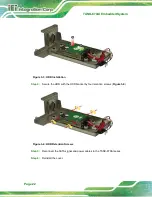
Step 2:
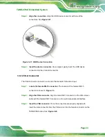
Align the connectors.
Align the USB device connector with one of the
connectors. See
Figure 3-21: USB Device Connection
Step 3:
Insert the device connector.
Once aligned, gently insert the USB device
connector into the on-board connector.
3.6.12 VGA Connector
The VGA connector connects to a monitor that accepts VGA video input.
Step 1:
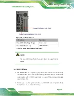
Locate the female DB-15 connector
. The location of the female DB-15
Step 2:
Align the VGA connector
. Align the male DB-15 connector on the VGA screen
cable with the female DB-15 connector on the external peripheral interface.
Step 3:
Insert the VGA connector
.
Once the connectors are properly aligned with,
insert the male connector from the VGA screen into the female connector on the
Summary of Contents for TANK-870AI SERIES
Page 14: ...TANK 870AI Embedded System Page XIV BIOS Menu 31 PCH Azalia Configuration Menu 99 ...
Page 15: ...TANK 870AI Embedded System Page 1 Chapter 1 1 Introduction ...
Page 27: ...TANK 870AI Embedded System Page 13 Chapter 2 2 Unpacking ...
Page 33: ...TANK 870AI Embedded System Page 19 Chapter 3 3 Installation ...
Page 57: ...TANK 870AI Embedded System Page 43 4 System Motherboard Chapter 4 ...
Page 69: ...TANK 870AI Embedded System Page 55 Chapter 5 5 BIOS ...
Page 114: ...TANK 870AI Embedded System Page 100 Appendix A A Regulatory Compliance ...
Page 119: ...TANK 870AI Embedded System Page 105 Appendix B B BIOS Options ...
Page 123: ...TANK 870AI Embedded System Page 109 Appendix C C Terminology ...
Page 127: ...TANK 870AI Embedded System Page 113 Appendix D D Safety Precautions ...
Page 132: ...TANK 870AI Embedded System Page 118 Appendix E E Digital I O Interface ...
Page 135: ...TANK 870AI Embedded System Page 121 Appendix F F Hazardous Materials Disclosure ...


