TANK-870AI Embedded System
Page 8
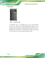
4 x USB 3.0 ports
4 x USB 2.0 ports
1 x Reset button
6 x LED indicators (
Section 1.7
1 x Power button
1 x VGA port
1 x HDMI+DP port
1 X DIO port
1 x To Ground
2 x Expansion slots
1 x ACC mode switch
1 x AT/ATX mode switch
1.7 LED Indicators
There are several indicators on the rear panel of the TANK-870AI series as shown in
Figure 1-4: TANK-870AI series LED Indicators
The descriptions of each LED indicator are listed below.
LED Indicator
Description
AT Power Mode
The current power mode status is AT mode.
Controlled by the AT/ATX power mode switch.
i
Shows IPMI status.
Power LED1
Breathing Orange:
Standby mode.
Power LED2
Solid blue:
Power-on mode.
Summary of Contents for TANK-870AI SERIES
Page 14: ...TANK 870AI Embedded System Page XIV BIOS Menu 31 PCH Azalia Configuration Menu 99 ...
Page 15: ...TANK 870AI Embedded System Page 1 Chapter 1 1 Introduction ...
Page 27: ...TANK 870AI Embedded System Page 13 Chapter 2 2 Unpacking ...
Page 33: ...TANK 870AI Embedded System Page 19 Chapter 3 3 Installation ...
Page 57: ...TANK 870AI Embedded System Page 43 4 System Motherboard Chapter 4 ...
Page 69: ...TANK 870AI Embedded System Page 55 Chapter 5 5 BIOS ...
Page 114: ...TANK 870AI Embedded System Page 100 Appendix A A Regulatory Compliance ...
Page 119: ...TANK 870AI Embedded System Page 105 Appendix B B BIOS Options ...
Page 123: ...TANK 870AI Embedded System Page 109 Appendix C C Terminology ...
Page 127: ...TANK 870AI Embedded System Page 113 Appendix D D Safety Precautions ...
Page 132: ...TANK 870AI Embedded System Page 118 Appendix E E Digital I O Interface ...
Page 135: ...TANK 870AI Embedded System Page 121 Appendix F F Hazardous Materials Disclosure ...


