IEI Technology IOWA-GX User Manual Download Page 88


IOWA-GX CPU Board


Page 70 


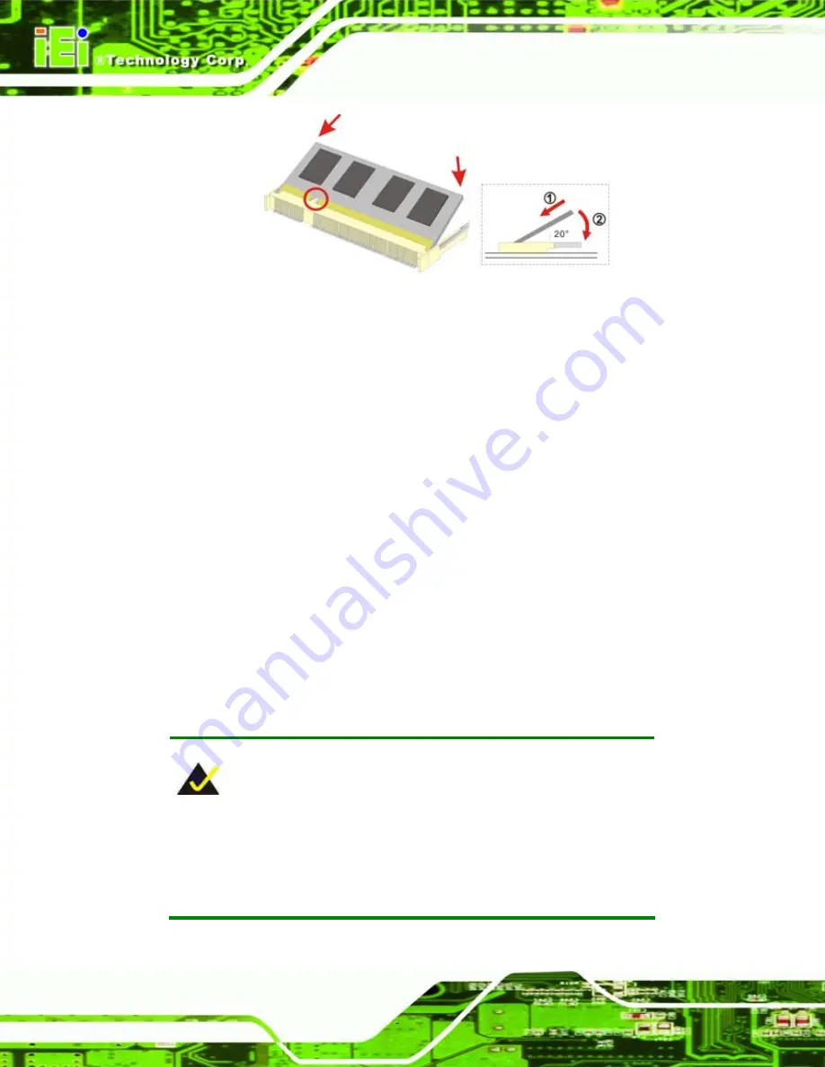
Figure 5-1: SO-DIMM Installation   

Step 1: 

Locate the SO-DIMM socket

. Place the IOWA-GX on an anti-static pad with the 

solder side facing up. 

Step 2: 

Align the SO-DIMM with the socket

. The SO-DIMM must be oriented in such a 

way that the notch in the middle of the SO-DIMM must be aligned with the 

plastic bridge in the socket. 

Step 3: 

Insert the SO-DIMM

. Push the SO-DIMM chip into the socket at an angle. (See 

Figure 5-1

Step 4: 

Open the SO-DIMM socket arms

. Gently pull the arms of the SO-DIMM socket 

out and push the rear of the SO-DIMM down. (See Figure 5-1

Step 5: 

Secure the SO-DIMM

. Release the arms on the SO-DIMM socket. They clip into 

place and secure the SO-DIMM in the socket.

Step 0:


5.4.2 CF Card Installation 


NOTE: 

The IOWA-GX can support both CF Type I cards and CF Type II cards. 

For the complete specifications of the supported CF cards please refer 

to 

Chapter 2

Summary of Contents for IOWA-GX

Page 1: ...IOWA GX CPU Board Page i Rev 1 11 March 2009...

Page 2: ...ii Revision Date Version Changes March 2009 1 11 Updated TTL pin7 description October 2007 1 10 Front panel connectors changed SATA RAID functionality added VGA modified to 15 pin D Sub Type June 200...

Page 3: ...rising out of the use or inability to use the product or documentation even if advised of the possibility of such damages This document contains proprietary information protected by copyright All righ...

Page 4: ...e A warning message is shown below WARNING This is an example of a warning message Failure to adhere to warning messages may result in permanent damage to the IOWA GX or personal injury to the user Pl...

Page 5: ...formation These messages should be read carefully as any directions or instructions contained therein can help avoid making mistakes Notes are easy to recognize The word note is written as NOTE both c...

Page 6: ...sales representative directly To contact an IEI sales representative please send an email to sales iei com tw The items listed below should all be included in the IOWA GX package 1 x IOWA GX Single B...

Page 7: ...imensions 10 2 3 DATA FLOW 11 2 4 AMD GEODE GX 466 CPU SUPPORT 12 2 4 1 CPU Core 12 2 4 2 Memory Controller 13 2 4 3 Video Processor 13 2 4 3 1 VGA Controller 14 2 4 3 2 TTL Controller 15 2 4 4 PCI Bu...

Page 8: ...utions 29 3 3 UNPACKING CHECKLIST 30 3 3 1 Package Contents 30 4 CONNECTOR PINOUTS 32 4 1 PERIPHERAL INTERFACE CONNECTORS 33 4 1 1 IOWA GX Layout 33 4 1 2 Peripheral Interface Connectors 34 4 1 3 Exte...

Page 9: ...hernet Connector 61 4 3 4 Serial Port Connector COM 1 62 4 3 5 VGA Connector 63 5 INSTALLATION 65 5 1 ANTI STATIC PRECAUTIONS 66 5 2 INSTALLATION CONSIDERATIONS 67 5 2 1 Installation Notices 67 5 2 2...

Page 10: ...88 5 8 4 Serial Device Connection 88 6 BIOS SCREENS 90 6 1 INTRODUCTION 91 6 1 1 Starting Setup 91 6 1 2 Using Setup 91 6 1 3 Getting Help 92 6 1 4 Unable to Reboot After Configuration Changes 92 6 1...

Page 11: ...Rebuild RAID Array 137 7 4 8 Select Boot Drive 138 8 SOFTWARE DRIVERS 139 8 1 AVAILABLE SOFTWARE DRIVERS 140 8 2 VGADRIVER INSTALLATION 141 8 3 AUDIO DRIVER INSTALLATION 144 8 4 LAN DRIVER 148 8 5 SA...

Page 12: ...LITY 182 F 1 COMPATIBLE OPERATING SYSTEMS 183 F 2 COMPATIBLE PROCESSORS 183 F 3 COMPATIBLE MEMORY MODULES 183 G HAZARDOUS MATERIALS DISCLOSURE 185 G 1 HAZARDOUS MATERIAL DISCLOSURE TABLE FOR IPB PRODU...

Page 13: ...ure 2 9 PCI to ISA Bridge 17 Figure 2 10 PCI to ISA Bridge 18 Figure 2 11 GeodeLink 19 Figure 2 12 IDE Controller 20 Figure 2 13 CF Type I CF Type II Socket 21 Figure 2 14 USB 22 Figure 2 15 BIOS 22 F...

Page 14: ...ations 54 Figure 4 19 COM 2 Connector Pinout Locations 55 Figure 4 20 TFT LCD Connector Pinout Locations 56 Figure 4 21 USB Connector Pinout Locations 58 Figure 4 22 VCC Power Connector Pinout Locatio...

Page 15: ...n Wizard 148 Figure 8 10 CD Main Menu 149 Figure 8 11 AMD LX GX CD Driver Menu 150 Figure 8 12 Locate the Setup Program Icon 150 Figure 8 13 Preparing Setup Screen 151 Figure 8 14 Install Wizard Welco...

Page 16: ...ket Pinouts 42 Table 4 8 DIO Connector Pinouts 43 Table 4 9 5V Fan Connector Pinouts 44 Table 4 10 34 pin FDD Connector Pinouts 45 Table 4 11 Front Panel Connector Pinouts 46 Table 4 12 IDE Connector...

Page 17: ...le 4 27 VGA Connector Pinouts 63 Table 5 1 Jumpers 72 Table 5 2 Panel CRT Selection Jumper Settings 73 Table 5 3 AT ATX Power Selection Jumper Settings 74 Table 5 4 COM3 Signal Selection 74 Table 5 5...

Page 18: ...enu 5 Advanced Chipset Features 105 BIOS Menu 6 Advanced Chipset Features 106 BIOS Menu 7 Integrated Peripherals 108 BIOS Menu 8 IT8888 ISA Decode IO 114 BIOS Menu 9 IT8888 ISA Decode Memory 116 BIOS...

Page 19: ...IOWA GX CPU Board Page 1 1 Introduction Chapter 1...

Page 20: ...RAM Multiple input output options include VGA and 24 bit TTL for video output a parallel port two serial ports an infrared port and 10 100BASE T Ethernet The IOWA GX supports up to two IDE drives and...

Page 21: ...upport for both legacy ISA and DMA direct memory access Multiple display output devices including VGA and TTL RAID options including RAID 1 for increased data safety and RAID 0 for improved drive perf...

Page 22: ...IOWA GX CPU Board Page 4 1 2 IOWA GX Overview Figure 1 2 IOWA GX Overview...

Page 23: ...The IOWA GX has the following connectors on board 1 x AT power connector 1 x Audio connector 1 x Backlight inverter connector 1 x Backplane to CPU card connector 1 x Battery connector 1 x CompactFlas...

Page 24: ...USB 2 0 connectors The IOWA GX has the following external peripheral interface connectors on the board rear panel 1 x Ethernet connector 1 x PS 2 keyboard connector 1 x Serial port connector 1 x VGA c...

Page 25: ...tek ALC203 LAN 10 100 Mbps Realtek RTL8100C Ethernet Chipset COM One external RS 232 serial port One internal RS 232 422 485 serial port header USB Four USB 2 0 devices supported IDE One 40 pin IDE co...

Page 26: ...IOWA GX CPU Board Page 8 2 Detailed Specifications Chapter 2...

Page 27: ...iew This chapter describes the specifications and on board features of the IOWA GX in detail 2 2 Dimensions 2 2 1 Board Dimensions The dimensions of the board are listed below Length 185mm Width 122mm...

Page 28: ...IOWA GX CPU Board Page 10 2 2 2 External Interface Panel Dimensions External peripheral interface connector panel dimensions are shown in Figure 2 2 Figure 2 2 External Interface Panel Dimensions mm...

Page 29: ...OWA GX motherboard comes with a AMD Geode GX 466 CPU and a AMD Geode GX CS5536 system chipset Figure 2 3 shows the data flow between the system chipset the CPU and other components installed on the mo...

Page 30: ...ow CPU Core GeodeLink Control Processor GeodeLink Interface Units GeodeLink Memory Controller Graphics Processor Display Controller Video Processor TFT Controller GeodeLink PCI Bridge Geode I O Compan...

Page 31: ...Branch performance enhanced with Branch Target Buffer BTB and Return Stack 2 4 2 Memory Controller The 64 bit DDR memory controller supports a 512MB maximum 200MHz DDR SO DIMM installed in a 200 pin S...

Page 32: ...a 15 pin VGA connector TFT displays are connected to a 40 pin crimp connector that is interfaced to the TTL controller The processor is then connected to the video processor The video processor is int...

Page 33: ...controller supports a maximum resolution of 1280 x 1024 pixels 2 4 4 PCI Bus The 66MHz AMD Geode GX 466 PCI bus complies with the PCI 2 2 specification The PCI bus supports write gathering and write p...

Page 34: ...d 100Mbps N way auto negotiation Supports 25MHz crystal or 25MHz OSC as the internal clock source Complies with PC99 PC2001 standards Supports ACPI power management Provides PCI bus master data transf...

Page 35: ...the ISA bus The 32 bit PCI bus interface on the IT8888F is compliant with PCI Specification v2 1 and supports both PCI Bus Master Slave Figure 2 9 PCI to ISA Bridge Some of the ITE IT8888F features in...

Page 36: ...the following features SATA specification revision 1 0 compliant PCI specification revision 2 2 compliant PCI Bus Power Management Specification revision 1 1 compliant Two independent channels to con...

Page 37: ...ned transactions Peer to peer communication Power management o 3 4W max 333MHz CRT o Block level gating o Active hardware power management o Software power management o Low power I O 2 5 AMD Geode CS5...

Page 38: ...troller PIO IDE transfers up to 16MB s and Ultra ATA transfers of 66MB s The integrated IDE interface is able to support the following IDE HDDs Ultra ATA 133 with data transfer rates up to 133MB s Ult...

Page 39: ...Controller Interface 5V 5V 5V 5V Table 2 1 Supported HDD Specifications 2 5 2 AMD Geode CS5536 Flash Interface The CompactFlash connector on the IOWA GX is connected to the flash interface on the AMD...

Page 40: ...e USB 1 1 and USB 2 0 standards 2 5 4 AMD Geode CS5536 LPC Bus Components The AMD Geode CS5536 LPC bus is connected to components listed below BIOS chipset Super I O chipset 2 5 4 1 BIOS Chipset The B...

Page 41: ...S 232 serial ports Parallel port Keyboard and mouse controller Some of the features of the Winbond W83627EHG are listed below LPC Spec 1 01 compliant Supports LDRQ LPC DMA SERIRQ Serial IRQ Integrated...

Page 42: ...oftware compatibility with the 8042 Support PS 2 mouse Support port 92 Support both interrupt and polling modes Fast Gate A20 and Hardware Keyboard Reset 8 Bit Timer Counter Support binary and BCD ari...

Page 43: ...nal parallel port Enhanced Parallel Port EPP Support Extended Capabilities Port ECP Compatible with IEEE 1284 specification Enhanced printer port back drive current protection 2 5 4 5 Winbond W83627EH...

Page 44: ...tible with IEEE 1284 specification Support Extended Capabilities Port ECP Compatible with IEEE 1284 specification Enhanced printer port back drive current protection 2 6 Environmental and Power Specif...

Page 45: ...sink must be installed on the CPU Thermal paste must be smeared on the lower side of the heat sink before it is mounted on the CPU Heat sinks are also mounted on the Northbridge and Southbridge chipse...

Page 46: ...IOWA GX CPU Board Page 28 3 Unpacking Chapter 3...

Page 47: ...ristband can help to prevent ESD from damaging the board Self grounding Before handling the board touch any grounded conducting material During the time the board is handled frequently touch any condu...

Page 48: ...ontact an IEI sales representative directly To contact an IEI sales representative please send an email to sales iei com tw 3 3 1 Package Contents The IOWA GX is shipped with the following components...

Page 49: ...IOWA GX CPU Board Page 31 Quantity Item and Part Number Image 1 Dual USB cable w bracket P N CB USB02 RS 1 Mini jumper pack 1 Quick installation guide 1 Utility CD Table 3 1 Package List Contents...

Page 50: ...IOWA GX CPU Board Page 32 4 Connector Pinouts Chapter 4...

Page 51: ...heral interface connector locations Section 4 1 2 lists all the peripheral interface connectors seen in Section 4 1 2 4 1 1 IOWA GX Layout Figure 4 1 shows the on board peripheral connectors rear pane...

Page 52: ...nectors on the IOWA GX Detailed descriptions of these connectors can be found below Connector Type Label AT power connector 4 pin header CN2 Audio CD In connector 4 pin header CN20 Audio connector 10...

Page 53: ...ctor 5 pin wafer CN7 Keyboard mouse connector 6 pin wafer CN25 Parallel port connector 26 pin header CN17 Power button connector 3 pin wafer CN3 SATA drive connector 7 pin SATA CN26 SATA drive connect...

Page 54: ...3 Table 4 2 Rear Panel Connectors 4 2 Internal Peripheral Connectors Internal peripheral connectors are found on the motherboard and are only accessible when the motherboard is outside of the chassis...

Page 55: ...12V Table 4 3 AT Power Connector Pinouts 4 2 2 Audio CD In Connector 4 pin CN Label CN20 CN Type 4 pin header CN Location See Figure 4 4 CN Pinouts See Table 4 4 The 4 pin audio CD in connector is con...

Page 56: ...gnal Right Table 4 4 Audio CD In Connector Pinouts 4 2 3 Audio Connector 10 pin CN Label CN19 CN Type 10 pin header CN Location See Figure 4 5 CN Pinouts See Table 4 5 The 10 pin audio connector is co...

Page 57: ...8 GND 9 MIC1 in 10 MIC2 in Table 4 5 Audio Connector Pinouts 10 pin 4 2 4 Battery Connector CN Label CN14 CN Type 2 pin wafer 1x2 CN Location See Figure 4 6 CN Pinouts See Table 4 6 The battery conne...

Page 58: ...Battery 2 Ground Table 4 6 Battery Connector Pinouts 4 2 5 Compact Flash Socket CN Label CN28 solder side CN Type 50 pin header 2x25 CN Location See Figure 4 7 CN Pinouts See Table 4 7 A CF Type I or...

Page 59: ...IOWA GX CPU Board Page 41 Figure 4 7 CF Card Socket Location PIN NO DESCRIPTION PIN NO DESCRIPTION 1 GND 26 GND 2 PIDE_3 27 PIDE_D11 3 PIDE_4 28 PIDE_D12 4 PIDE_5 29 PIDE_D13...

Page 60: ...VCC5 38 VCC5 14 GND 39 CSEL 15 GND 40 N C 16 GND 41 PIDE_RST 17 GND 42 PIDE_RDY 18 PIDE_A2 43 PIDE_DRQ 19 PIDE_A1 44 PIDE_ACK 20 PIDE_A0 45 PDASP 21 PIDE_D0 46 IDE_CABLEID 22 PIDE_D1 47 PIDE_D8 23 PI...

Page 61: ...programmable Figure 4 8 DIO Connector Locations PIN NO DESCRIPTION PIN NO DESCRIPTION 1 Ground 2 VCC 3 Output 0 4 Output 1 5 Output 2 6 Output 3 7 Input 0 8 Input 1 9 Input 2 10 Input 3 Table 4 8 DIO...

Page 62: ...lease note that only specified fans can issue the rotation signals Figure 4 9 5V Fan Connector Location PIN NO DESCRIPTION 1 GND 2 12V 3 Fan Speed Detect Table 4 9 5V Fan Connector Pinouts 4 2 8 Flopp...

Page 63: ...6 N C 7 GND 8 INDEX 9 GND 10 MOTOR ENABLE A 11 GND 12 DRIVE SELECT B 13 GND 14 DRIVE SELECT A 15 GND 16 MOTOR ENABLE B 17 GND 18 DIRECTION 19 GND 20 STEP 21 GND 22 WRITE DATA 23 GND 24 WRITE GATE 25...

Page 64: ...ector connects to the power button reset button and hard drive LEDs located on the front panel of the chassis Figure 4 11 Front Panel Connector Pinout Locations PIN NO DESCRIPTION PIN NO DESCRIPTION 1...

Page 65: ...gure 4 12 CN Pinouts See Table 4 12 One 40 pin IDE device connector on the IOWA GX supports connectivity to two hard disk drives Figure 4 12 IDE Device Connector Locations PIN NO DESCRIPTION PIN NO DE...

Page 66: ...GROUND 25 IOR 26 GROUND 27 IDE CHRDY 28 GROUND 29 IDE DACK 30 GROUND DEFAULT 31 INTERRUPT 32 N C 33 SA1 34 N C 35 SA0 36 SA2 37 HDC CS0 38 HDC CS1 39 HDD ACTIVE 40 GROUND Table 4 12 IDE Connector Pin...

Page 67: ...NC 3 RxD2 4 GND 5 TxD2 Table 4 13 Infrared Connector Pinouts 4 2 12 Inverter Power Connector CN Label CN7 CN Type 5 pin wafer 1x5 CN Location See Figure 4 14 CN Pinouts See Table 4 14 The backlight in...

Page 68: ...5 LCD Enable Table 4 14 Panel Backlight Connector Pinouts 4 2 13 Keyboard Mouse Connector CN Label CN25 CN Type 6 pin header 1x6 CN Location See Figure 4 15 CN Pinouts See Table 4 15 The keyboard and...

Page 69: ...DATA 5 KB CLK 6 GROUND Table 4 15 Keyboard Mouse Connector Pinouts 4 2 14 Parallel Port Connector CN Label CN17 CN Type 26 pin box header CN Location See Figure 4 16 CN Pinouts See Table 4 16 The 26 p...

Page 70: ...TA 1 6 INITIALIZE 7 DATA 2 8 PRINTER SELECT LN 9 DATA 3 10 GROUND 11 DATA 4 12 GROUND 13 DATA 5 14 GROUND 15 DATA 6 16 GROUND 17 DATA 7 18 GROUND 19 ACKNOWLEDGE 20 GROUND 21 BUSY 22 GROUND 23 PAPER EM...

Page 71: ...ured Figure 4 17 ATX Power Supply Enable Connector Location PIN NO DESCRIPTION 1 GND 2 PS ON 3 5V Standby Table 4 17 ATX Power Supply Enable Connector Pinouts 4 2 16 SATA Drive Connectors CN Label CN2...

Page 72: ...A Drive Connector Pinouts 4 2 17 Serial Port Connector RS 232 422 485 CN Label CN18 CN Type 14 pin header 2x7 CN Location See Figure 4 19 CN Pinouts See Table 4 19 The 10 pin serial port connector pro...

Page 73: ...Send RTS 5 Transmit Data TXD 6 Clear To Send CTS 7 Data Terminal Ready DTR 8 Ring Indicator RI 9 Ground GND 10 Ground GND 11 TxD485 12 TxD485 13 RxD485 14 RxD485 Table 4 19 COM 2 Connector Pinouts 4...

Page 74: ...IOWA GX CPU Board Page 56 Figure 4 20 TFT LCD Connector Pinout Locations PIN NO DESCRIPTION PIN NO DESCRIPTION 1 LCD_VCC 2 LCD_VCC 3 GND 4 GND 5 LCD_VCC 6 LCD_VCC 7 I_SDA 8 GND 9 TFT_B0 10 TFT_B1...

Page 75: ...T_R0 26 TFT_R1 27 TFT_R2 28 TFT_R3 29 TFT_R4 30 TFT_R5 31 TFT_R6 32 TFT_R7 33 GND 34 GND 35 PFSCLK 36 VSYNC 37 LCD_EN 38 HSYNC 39 I_SCL 40 DISPEN Table 4 20 TFT LCD Port Connector Pinouts NOTE For 18...

Page 76: ...DESCRIPTION 1 VCC_USB 2 USB_GND 3 D1F 4 D2F 5 D1F 6 D2F 7 USB_GND 8 VCC_USB Table 4 21 USB Port Connector Pinouts 4 2 20 VCC Power Connectors CN Label CN1 CN Type 3 pin header 1 x 3 CN Location See F...

Page 77: ...Power Connector Pinouts 4 3 External Peripheral Interface Connectors 4 3 1 External Peripheral Interface Connector Overview The IOWA GX external peripheral interface connectors are listed below and sh...

Page 78: ...2 Keyboard Mouse Connector CN Label CN24 CN Type PS 2 CN Location See Figure 4 23 CN Pinouts See Figure 4 24 and Table 4 23 The PS 2 connector can be connected to a keyboard or mouse Figure 4 24 PS 2...

Page 79: ...4 23 CN Pinouts See Table 4 24 The RJ 45 Ethernet connector on the IOWA GX provides connectivity to a 10 100 megabit Ethernet connection between the IOWA GX and a Local Area Network LAN through a netw...

Page 80: ...0MB OFF 10MB YELLOW ON Linked Flashing Activity Table 4 25 J7 Connector LEDs 4 3 4 Serial Port Connector COM 1 CN Label CN21 CN Type DB 9 connector CN Location See Figure 4 23 CN Pinouts See Table 4 2...

Page 81: ...3 CN Pinouts See Figure 4 27 and Table 4 27 The standard 15 pin female DB15 VGA connector connects to a CRT or LCD monitor directly PIN DESCRIPTION PIN DESCRIPTION PIN DESCRIPTION 1 RED 6 GROUND 11 NC...

Page 82: ...IOWA GX CPU Board Page 64 Figure 4 27 VGA Connector...

Page 83: ...IOWA GX CPU Board Page 65 5 Installation Chapter 5...

Page 84: ...ectrical component is handled the following anti static precautions are strictly adhered to Wear an anti static wristband Wearing a simple anti static wristband can help to prevent ESD from damaging t...

Page 85: ...cribed in this manual should be carefully followed in order to prevent damage to the IOWA GX IOWA GX components and injury to the user Before and during the installation please DO the following Read t...

Page 86: ...klist is provided to ensure the IOWA GX is properly installed All the items in the packing list are present The CPU is installed The CPU cooling kit is properly installed A compatible memory module is...

Page 87: ...all out of the box Make sure all the components in the checklist shown in Section 3 3 are present 5 4 SO DIMM and CompactFlash Card Installation 5 4 1 SO DIMM Installation WARNING Using incorrectly sp...

Page 88: ...et Step 3 Insert the SO DIMM Push the SO DIMM chip into the socket at an angle See Figure 5 1 Step 4 Open the SO DIMM socket arms Gently pull the arms of the SO DIMM socket out and push the rear of th...

Page 89: ...e IOWA GX on an anti static pad with the solder side facing up Locate the CF card Step 2 Align the CF card Make sure the CF card is properly aligned with the CF socket Step 3 Insert the CF card Gently...

Page 90: ...of the jumper with the plastic clip and to OPEN a jumper means removing the plastic clip from a jumper Before the IOWA GX is installed in the system the jumpers must be set in accordance with the des...

Page 91: ...3 pin header Jumper Settings See Table 5 2 Jumper Location See Figure 5 3 The Panel CRT selection jumper selects which video output is used The Panel CRT selection jumper settings are shown in Table 5...

Page 92: ...e shown in Table 5 2 Pin Description Short AT Default Open ATX Table 5 3 AT ATX Power Selection Jumper Settings 5 5 3 COM3 Signal Selection Jumper Label JP3 Jumper Type 3 pin header Jumper Settings Se...

Page 93: ...correct voltage Jumper Label JP5 Jumper Type 3 pin header Jumper Settings See Table 5 5 Jumper Location See Figure 5 3 Sets the voltage of the TTL panel connector Pin Description Short 1 2 3 3V Defaul...

Page 94: ...em and hot air to move out The IOWA GX must be installed in a chassis with ventilation holes on the sides allowing airflow to travel through the heat sink surface In a system with an individual power...

Page 95: ...ct your IOWA GX vendor reseller or an IEI sales representative at sales iei com tw or visit the IEI website http www ieiworld com tw to find out more about the available chassis 5 6 3 CPU Card Install...

Page 96: ...EI Provided Cables 5 7 2 ATA Flat Cable Connection The ATA 66 100 flat cable connects to the IOWA GX to one or two IDE devices To connect an IDE HDD to the IOWA GX please follow the instructions below...

Page 97: ...rStep 0 5 7 3 Audio Kit Installation The Audio Kit that came with the IOWA GX connects to the 10 pin audio connector on the IOWA GX The audio kit consists of three audio jacks One audio jack Mic In co...

Page 98: ...onnect the audio devices Connect one speaker to the line in audio jack one speaker to the line out audio jack and a microphone to the Mic in audio jack Step 0 5 7 4 SATA Drive Connection The IOWA GX i...

Page 99: ...onboard SATA drive connector See Figure 5 6 Figure 5 6 SATA Drive Cable Connection Step 3 Connect the cable to the SATA disk Connect the connector on the other end of the cable to the connector at th...

Page 100: ...onnect the USB cable connector please follow the steps below Step 5 Locate the connectors The locations of the USB connectors are shown in Chapter 3 WARNING If the USB pins are not properly aligned th...

Page 101: ...ep 8 Attach the bracket to the chassis The USB 2 0 connectors are attached to a bracket To secure the bracket to the chassis please refer to the installation instructions that came with the chassis St...

Page 102: ...pins are properly aligned WARNING The diagram below is merely for illustration The configuration and connection of the cables from the TFT LCD screen being installed may be different Please refer to...

Page 103: ...ter Connection 5 8 External Peripheral Interface Connection The following external peripheral devices can be connected to the external peripheral interface connectors Serial port devices VGA monitors...

Page 104: ...wn in Chapter 3 Step 6 Align the VGA connector Align the male DB 15 connector on the VGA screen cable with the female DB 15 connector on the external peripheral interface Step 7 Insert the VGA connect...

Page 105: ...d and mouse to the IOWA GX Step 1 Locate the dual PS 2 connector The location of the PS 2 connector is shown in Chapter 3 Step 2 Insert the keyboard mouse connector Insert the PS 2 connector on the en...

Page 106: ...shown in Chapter 4 Step 2 Align the connectors Align the RJ 45 connector on the LAN cable with one of the RJ 45 connectors on the IOWA GX See Figure 5 13 Figure 5 13 LAN Connection Step 3 Insert the...

Page 107: ...al connector Insert the DB 9 connector of a serial device into the DB 9 connector on the external peripheral interface See Figure 5 14 Figure 5 14 Serial Device Connector Step 3 Secure the connector S...

Page 108: ...IOWA GX CPU Board Page 90 6 BIOS Screens Chapter 6...

Page 109: ...s Del to enter SETUP message appears on the screen If the message disappears restart the computer and try again 6 1 2 Using Setup Use the arrow keys to highlight items press ENTER to select use the PA...

Page 110: ...0 Save changes and Exit BIOS Table 6 1 BIOS Navigation Keys 6 1 3 Getting Help When F1 is pressed a small help window describing the appropriate keys to use and the possible selections for the highlig...

Page 111: ...and the configuration options available to users The following menu options are seen in BIOS Menu 1 Standard CMOS Features Changes the basic system configuration Advanced BIOS Features Changes the ad...

Page 112: ...all a supervisor password select this field and enter the password After this option is selected a red dialogue box appears with Enter Password Type the password and press ENTER Retype the original pa...

Page 113: ...Exit Without Saving Use the Exit Without Saving option to exit the BIOS menus without saving any configuration changes 6 2 Standard CMOS Features Use the Standard CMOS Features BIOS menu BIOS Menu 2 t...

Page 114: ...figurations are changed or set in the IDE Configuration menu BIOS Menu 3 If an IDE device is detected and one of the above listed two BIOS configuration options is selected the IDE configuration optio...

Page 115: ...ase Memory is NOT user configurable The POST determines the amount of base or conventional memory installed in the system The value of the base memory is typically 512K for systems with 512K memory in...

Page 116: ...IDE HDD Auto Detection and press ENTER BIOS automatically detects the HDD type Do not set this option manually IDE Primary Master Auto Use the IDE Primary Master option to activate or deactivate the f...

Page 117: ...Access Mode option to determine the hard disk BIOS translation modes Most systems now use hard drives with large capacities and therefore either the LBA translation mode or auto mode should be select...

Page 118: ...tes how many logical heads are on the HDD installed in the system Precomp The Precomp specification indicates on what track the write precompensation begins Landing Zone The Landing Zone specification...

Page 119: ...Self Test Enabled Use the Quick Power On Self Test option to speed up the POST after the computer is turned on If enabled BIOS shortens or skips some POST check items Disabled Normal POST occurs afte...

Page 120: ...ATA IDE use in DOS mode Boot Device Use the Boot Device options to select the order of the devices the system boots from There are three boot device configuration options First Boot Device Default Flo...

Page 121: ...t found Enabled Default The system looks for second and third boot devices if the first one is not found Boot Up Numlock Status On Use the Boot Up Numlock Status option to specify the default state of...

Page 122: ...Self Monitoring Analysis and Reporting Technology SMART feature can help predict impending drive failures The S M A R T BIOS option enables or disables this function Auto BIOS to auto detects if the h...

Page 123: ...mount of memory allocated to the integrated graphics processor when the system boots up Configuration options are None 4MB 6MB 8MB Default 12MB 16MB Onboard Audio Enabled Use the Onboard Audio option...

Page 124: ...sabled Chipset USB 2 0 controller disabled Onboard USB 1 1 Enabled Use the Onboard USB 1 1 option to enable or disable the chipset USB controller Enabled DEFAULT Chipset USB 1 1 controller enabled Dis...

Page 125: ...Please refer to the technical documents that came with the flat panel PC to ensure the correct settings are selected The following options are available 640x480 DEFAULT 800x600 1024x768 6 5 Integrated...

Page 126: ...specify if the system uses the integrated primary IDE channel or not Disabled The primary IDE channel is not used Enabled Default The primary IDE channel is used Drive PIO Mode Auto Use the Drive PIO...

Page 127: ...e the IDE UDMA option below to select the Ultra DMA UDMA mode for the following HDDs IDE Primary Master UDMA IDE Primary Slave UDMA Auto Default The computer selects the correct UDMA Disabled The UDMA...

Page 128: ...tion to select the I O address and IRQ for the onboard serial port 2 The serial port can be disabled or the I O address and the IRQ can be automatically selected by the BIOS The Onboard Serial Port 2...

Page 129: ...peration mode Half Default Half duplex mode allows transmission in one direction at a time only Full Full duplex mode allows transmission in both directions at the same time Use IR Pins IR Rx2Tx2 Use...

Page 130: ...RQ4 2E8 IRQ3 Parallel Port Mode Normal The Parallel Port Mode selection selects the mode the parallel port operates in Normal DEFAULT The normal parallel port mode is the standard mode for parallel po...

Page 131: ...the two are much faster than the Normal mode The parallel port becomes compatible with EPP devices described above EPP Mode Select EPP1 7 The Parallel Port EPP Type option is only available if the Pa...

Page 132: ...s BIOS Menu 8 IT8888 ISA Decode IO Decode IO Space x Disabled Use the Decode IO Space x option to enable or disable the decoding of a particular IO space Disabled Default IO space decoding is disabled...

Page 133: ...aces are shown below IO Space 0 0100 IO Space 1 0200 IO Space 2 0280 IO Space 3 0300 IO Space 4 0380 IO Space 5 0A78 Decode IO Size x Varying defaults Use the Decode IO Size option to manually enter t...

Page 134: ...ular IO space Disabled Default Memory space decoding is disabled Enabled Memory space decoding is enabled and the options below are accessible Decode Memory Speed x Medium Speed Use the Decode Memory...

Page 135: ...aces are shown below Memory Space 0 D00 Memory Space 1 000 Memory Space 2 000 Memory Space 3 000 Decode Memory Size x Varying defaults Use the Decode Memory Size option to manually enter the size of t...

Page 136: ...Disabled Use the DDMAx option to enable or disable DDMA support Disabled Default DDMA support is disabled Enabled DDMA support is enabled 6 6 Power Management Setup Use the Power Management Setup menu...

Page 137: ...r management profile the system will use ACPI Default ACPI is used APM Advanced Power Management is used Power On by Alarm Disabled The Power On by Alarm determines when the computer will be roused fr...

Page 138: ...the alarm goes off 6 7 PnP PCI Configurations Use the PnP PCI Configurations menu BIOS Menu 12 to set the plug and play and PCI options BIOS Menu 12 PnP PCI Configurations Init Display First Internal...

Page 139: ...cally IRQs DMA and memory base address fields cannot be set manually Auto ESCD Default BIOS automatically configures plug and play devices as well as boot devices Manual Manually configure the plug an...

Page 140: ...s assigned to legacy ISA for devices compliant with the original PC AT bus specification PCI ISA PNP for devices compliant with the Plug and Play standard whether designed for PCI or ISA bus architect...

Page 141: ...assigned to DMA 7 assigned to The above options all have the following default options PCI ISA PnP The DMA is reserved by BIOS for PCI and ISA PnP devices Legacy ISA Default The DMA is assigned to leg...

Page 142: ...perating parameters that are essential to the stable operation of the system BIOS Menu 15 PC Health Status The following system parameters are monitored by the PC Health Status menu System Temperature...

Page 143: ...IOWA GX CPU Board Page 125 Vcore Vmem VCC3 5 V 12 V VCC VBAT 5VSB...

Page 144: ...IOWA GX CPU Board Page 126 7 ALi RAID Setup Appendix 7...

Page 145: ...m as a contingent storage space The operating system will not be able to distinguish the physical disk drives contained in a RAID configuration 7 1 1 Precautions One key benefit a RAID configuration b...

Page 146: ...To access the Ali RAID Utility please follow the steps below Step 1 Connect SATA drives to the system Connect two SATA drives to the system Make sure the drives have the same capacity are the same ty...

Page 147: ...rt BIOS option is enabled save and exit the BIOS Step 4 Reboot the system Reboot the system after saving and exiting the BIOS Step 5 Press Ctrl A When the following screen appears press Ctrl A to ente...

Page 148: ...lete All RAID Setting Partition Figure A 2 RAID BIOS Setup Utility Step 7 Configure the RAID settings Use the RAID BIOS Setup Utility in Chapter 6 to configure the RAID array Brief descriptions are gi...

Page 149: ...ate RAID 0 Striping for Performance and press ENTER A flashing S appears on the Drive Menu where the member drives to be included in the RAID 0 array can be chosen Step 2 Select RAID array drive membe...

Page 150: ...ected on the same IDE channel cannot be selected as the members of a RAID 0 array Avoid mixing PATA and SATA disk drives in a RAID 0 array 2 Always use disk drives of the same capacity to create a RAI...

Page 151: ...Drive Menu where the member drives to be included in the RAID 0 array can be chosen Step 2 Select RAID array drive members Use the space bar to select members of the RAID array The flashing cursor cha...

Page 152: ...ected on the same IDE channel cannot be selected as the members of a RAID 1 array Avoid mixing PATA and SATA disk drives in a RAID 1 array 2 Always use disk drives of the same capacity to create a RAI...

Page 153: ...acity Use the arrow keys to highlight Create JBOD for Integrated Capacity and press ENTER A flashing J appears on the Drive Menu where the member drives to be included in the JBOD array can be chosen...

Page 154: ...he stripe size effects RAID 0 arrays Configurable options are 64K default 32K 16K 8K 4K Select a small stripe size if the I Os to the hard drives are small and occur randomly Choose a larger stripe si...

Page 155: ...keys to highlight Delete All RAID Setting Partition and press ENTER Step 2 Confirm delete The Data on RAID drives will be erased Y N confirm box appears Press Y Step 0 7 4 7 Rebuild RAID Array The Re...

Page 156: ...array may vary depending on the size of stored data disk drive capacity and drive performance 7 4 8 Select Boot Drive Step 1 Select the Boot Drive Use the arrow keys to highlight Select Boot Drive an...

Page 157: ...IOWA GX CPU Board Page 139 8 Software Drivers Chapter 8...

Page 158: ...A GX motherboard installed in the subsystem VGA Driver Audio Driver LAN Driver SATA RAID Driver ISA Driver All five drivers can be found on the CD that came with the motherboard To install the drivers...

Page 159: ...lation instructions are for a system running Windows XP To install the VGA driver please follow the steps below Step 1 Turn the system on Step 2 After the system with Windows XP is turned on for the f...

Page 160: ...the third option in Figure 8 1 Step 4 Insert the disk that came with the system Step 5 Click NEXT to continue Figure 8 2 Select the Installation Method Step 6 Select if the system should automaticall...

Page 161: ...Board Page 143 Figure 8 3 VGA Driver Installation Step 9 If the driver cannot be located by the system the user is prompted to specify the location of the driver See Figure 8 4 Figure 8 4 VGA Driver I...

Page 162: ...s_v1 04 00 Step 11 Once located the driver is installed Step 12 When the driver installation is complete click FINISH to close the installation wizard See Figure 8 5 Step 12 Figure 8 5 Close the VGA D...

Page 163: ...t time the message in Figure 8 6 appears Figure 8 6 Audio Driver Start Up Screen Step 15 If the system should access the Windows Update site select either the first option or second option in Figure 8...

Page 164: ...shown in Figure 8 7 Step 19 Click NEXT to continue Step 20 The system starts to install the driver See Figure 8 3 NOTE In some cases the Audio driver may already be present in the OS The OS then auto...

Page 165: ...IOWA GX CPU Board Page 147 Figure 8 8 Audio Driver Installation Step 21 When the driver installation is complete click FINISH to close the installation wizard See Figure 8 9 Step 21...

Page 166: ...the Audio Driver Installation Wizard 8 4 LAN Driver To install the LAN driver please follow the steps below Step 22 Insert the CD that came with the system Step 23 The screen shown in Figure 8 10 app...

Page 167: ...window Figure 8 11 appears listing all the available drives Step 26 Select LAN in the screen shown in Figure 8 11 Click LAN from the AMD LX GX CD Driver Menu Figure 8 11 to open a window to the X LAN...

Page 168: ...he RTL8100C folder Step 28 Locate the Setup program icon Figure 8 12 Figure 8 12 Locate the Setup Program Icon Step 29 Double click the Setup program icon in Figure 8 12 Step 30 The Install Shield Wiz...

Page 169: ...tep 31 Once initialized the Install Wizard welcome screen appears Figure 8 14 Figure 8 14 Install Wizard Welcome Screen Step 32 Click NEXT to continue the installation or CANCEL to stop the installati...

Page 170: ...izard Step 36 Once the installation process is complete the computer may be restarted immediately or later Select the preferred option and click FINISH to complete the installation process and exit St...

Page 171: ...p 2 Locate the Setup program icon Figure 8 16 Figure 8 16 Locate the Setup Program Icon Step 3 The Install Shield Wizard Figure 8 17 is prepared to guide the user through the rest of the process Figur...

Page 172: ...ard Page 154 Step 4 Once initialized the Install Wizard welcome screen appears Figure 8 18 Figure 8 18 Install Wizard Welcome Screen Step 5 Click NEXT to continue the installation or CANCEL to stop th...

Page 173: ...IOWA GX CPU Board Page 155 Step 6 The Install Wizard starts to install the driver Figure 8 19 Figure 8 19 Installing Screen...

Page 174: ...IOWA GX CPU Board Page 156 Step 7 A Digital Signal Not Found screen appears Figure 8 20 Click YES to continue the installation process Figure 8 20 RAID Driver Digital Signal...

Page 175: ...screen appears Figure 8 21 Figure 8 21 InstallShield Wizard Complete Screen Step 9 Once the installation process is complete the computer may be restarted immediately or later Select the preferred op...

Page 176: ...ions are for a system running Windows XP To install the IT8888 ISA Bridge driver please follow the steps below Step 1 Turn the system on Step 2 After the system with Windows XP is turned on for the fi...

Page 177: ...the third option in Figure 8 22 Step 4 Insert the disk that came with the system Step 5 Click NEXT to continue Figure 8 23 Select the Installation Method Step 6 Select if the system should automatical...

Page 178: ...tects and installs the driver as in this case If the OS does not have the driver the disk needs to be inserted and the driver located in the following directory E IT8888 Figure 8 24 IT8888 ISA Bridge...

Page 179: ...IOWA GX CPU Board Page 161 Figure 8 25 Close the IT8888 ISA Bridge Driver Installation Wizard...

Page 180: ...IOWA GX CPU Board Page 162 A BIOS Options Appendix A...

Page 181: ...sword 94 Set User Password 94 Save Exit Setup 95 Exit Without Saving 95 Date Day mm dd yyyy 95 Time hh mm ss 96 IDE Master and IDE Slave 96 Drive A None 96 Halt On All But Keyboard 96 Base Memory 97 E...

Page 182: ...ding Zone 100 Sector 100 Quick Power On Self Test Enabled 101 Boot From LAN Control Disabled 101 SATA Boot ROM Control Disabled 102 Boot Device 102 Boot Other Device Enabled 103 Boot Up Numlock Status...

Page 183: ...p IDE Channel 1 Enabled 108 Drive PIO Mode Auto 108 IDE UDMA Auto 109 IDE HDD Block Mode Enabled 109 Onboard Serial Port 1 3F8 IRQ4 110 Onboard Serial Port 2 2F8 IRQ3 110 UART 2 Mode Standard 110 RxD...

Page 184: ...IO Speed x Slow Speed 114 Decode IO Address x 15 0 Varying defaults 115 Decode IO Size x Varying defaults 115 Decode Memory Space x Disabled 116 Decode Memory Speed x Medium Speed 116 Decode Memory A...

Page 185: ...CPU Board Page 167 System Time 120 Init Display First Internal VGA 120 Resources Controlled By Auto ESCD 121 IRQ Resources Press Enter 121 Memory Resources Press Enter 122 System Temperature 124 Volta...

Page 186: ...IOWA GX CPU Board Page 168 B Terminology Appendix B...

Page 187: ...t APM application program interface API enables the inclusion of power management in the BIOS ARMD An ATAPI Removable Media Device ARMD is any ATAPI device that supports removable media besides CD and...

Page 188: ...t data bus and have separate electrical contacts on each side of the module DIO The digital inputs and digital outputs are general control signals that control the on off circuit of external devices o...

Page 189: ...l memory cache built into the system processor L2 Cache The Level 2 Cache L2 Cache is an external processor memory cache LCD Liquid crystal display LCD is a flat low power display device that consists...

Page 190: ...Analysis and Reporting Technology S M A R T refers to automatic status checking technology implemented on hard disk drives UART Universal Asynchronous Receiver transmitter UART is responsible for asy...

Page 191: ...IOWA GX CPU Board Page 173 C DIO Interface Appendix C...

Page 192: ...further information please refer to the Winbond datasheet for the Winbond W83627EHG Super I O chipset C 2 DIO Connector Pinouts The following table describes how the DIO connector pins are connected t...

Page 193: ...l I O input functions is listed below MOV AX 6F08H Sets the digital port as input INT 15H Initiates the INT 15H BIOS call C 3 2 Enable the DIO Output Function The BIOS interrupt call INT 15H controls...

Page 194: ...IOWA GX CPU Board Page 176 D Watchdog Timer Appendix D...

Page 195: ...function call INT 15H is used to control the Watchdog Timer INT 15H AH 6FH Sub function AL 2 Sets the Watchdog Timer s period BL Time out value Its unit second is dependent on the item Watchdog Timer...

Page 196: ...stem resets Example program INITIAL TIMER PERIOD COUNTER W_LOOP MOV AX 6F02H setting the time out value MOV BL 30 time out value is 48 seconds INT 15H ADD THE APPLICATION PROGRAM HERE CMP EXIT_AP 1 is...

Page 197: ...IOWA GX CPU Board Page 179 E Address Mapping Appendix E...

Page 198: ...0FF Numeric data processor 1F0 1F7 Primary IDE Channel 2F8 2FF Serial Port 2 COM2 378 37F Parallel Printer Port 1 LPT1 3B0 3BB AMD Graphics Controller 3C0 3DF AMD Graphics Controller 3F6 3F6 Primary I...

Page 199: ...SATA IRQ4 COM1 IRQ12 PS 2 mouse IRQ5 SMBus Controller IRQ13 FPU IRQ6 FDC IRQ14 Primary IDE IRQ7 Available IRQ15 Secondary IDE Table E 3 IRQ Mapping Table E 4 DMA Channel Assignments Channel Function 0...

Page 200: ...IOWA GX CPU Board Page 182 F Compatibility Appendix F...

Page 201: ...The following operating systems have been successfully run on the IOWA GX MS DOS 6 22 Microsoft Windows XP 32 bit Fedora Core 5 Red Hat 9 0 F 2 Compatible Processors The following processors have been...

Page 202: ...ard Page 184 The following memory modules have been successfully tested on the IOWA GX Manufacturer Interface Capacity Speed Twinmos DDR 256MB DDR333 DSL DDR 512MB DDR400 Adata DDR 512MB DDR333 DAL DD...

Page 203: ...IOWA GX CPU Board Page 185 G Hazardous Materials Disclosure Appendix G...

Page 204: ...esences of small quantities of certain materials in the product and is applicable to China RoHS only A label will be placed on each product to indicate the estimated Environmentally Friendly Use Perio...

Page 205: ...Board X O O O O X Metal Fasteners X O O O O O Cable Assembly X O O O O X Fan Assembly X O O O O X Power Supply Assemblies X O O O O X Battery O O O O O O O This toxic or hazardous substance is contain...

Page 206: ...IOWA GX CPU Board Page 188 RoHS RoHS Pb Hg Cd CR VI PBB PBDE X O O O O X X O O O O X X O O O O X X O O O O O X O O O O X X O O O O X X O O O O X O O O O O O O SJ T11363 2006 X SJ T11363 2006...

Page 207: ...IOWA GX CPU Board Page 189 Index...

Page 208: ...nouts 38 audio connector CD in 37 location and pinouts 37 B backlight inverter connector 5 49 location and pinouts 49 backplane 77 installation 77 backplane to mainboard connector 5 backup battery 39...

Page 209: ...DB 15 connector 86 DB 9 connector 89 digital input output connector 43 location and pinouts 43 dimensions 9 board 9 external peripheral interface connector panel 10 dual port USB cable 82 E electrost...

Page 210: ...ouse connector 50 location and pinouts 50 KINO 6612 36 L LAN connection 88 LCD display 49 backlight inverter connector 49 LCD panel 55 LED 62 RJ 45 Ethernet connection status 62 LPC bus 22 LVDS 107 LV...

Page 211: ...pinouts 62 COM 2 location and pinouts 54 connector location and pinouts 54 62 serial port devices 54 RS 232 serial port devices 54 S Safety Precautions 181 SATA 18 140 152 SATA drive controller 18 SAT...

Page 212: ...connection 83 connectors 82 devices 58 USB 1 1 3 USB 1 1 58 USB 1 1 3 58 USB cable dual port 82 USB connector internal 6 58 location and pinouts 58 V VCC power connector 58 location and pinouts 58 VGA...

Reviews: