IDEAL istor HE260 Installation And Servicing Download Page 66

66

istor system store - 

Installation and Servicing

FAULT FINDING

F

AUL

T FINDING F

AUL

T FINDING F

AUL

T FINDING F

AUL

T FINDING F

AUL

T FINDING

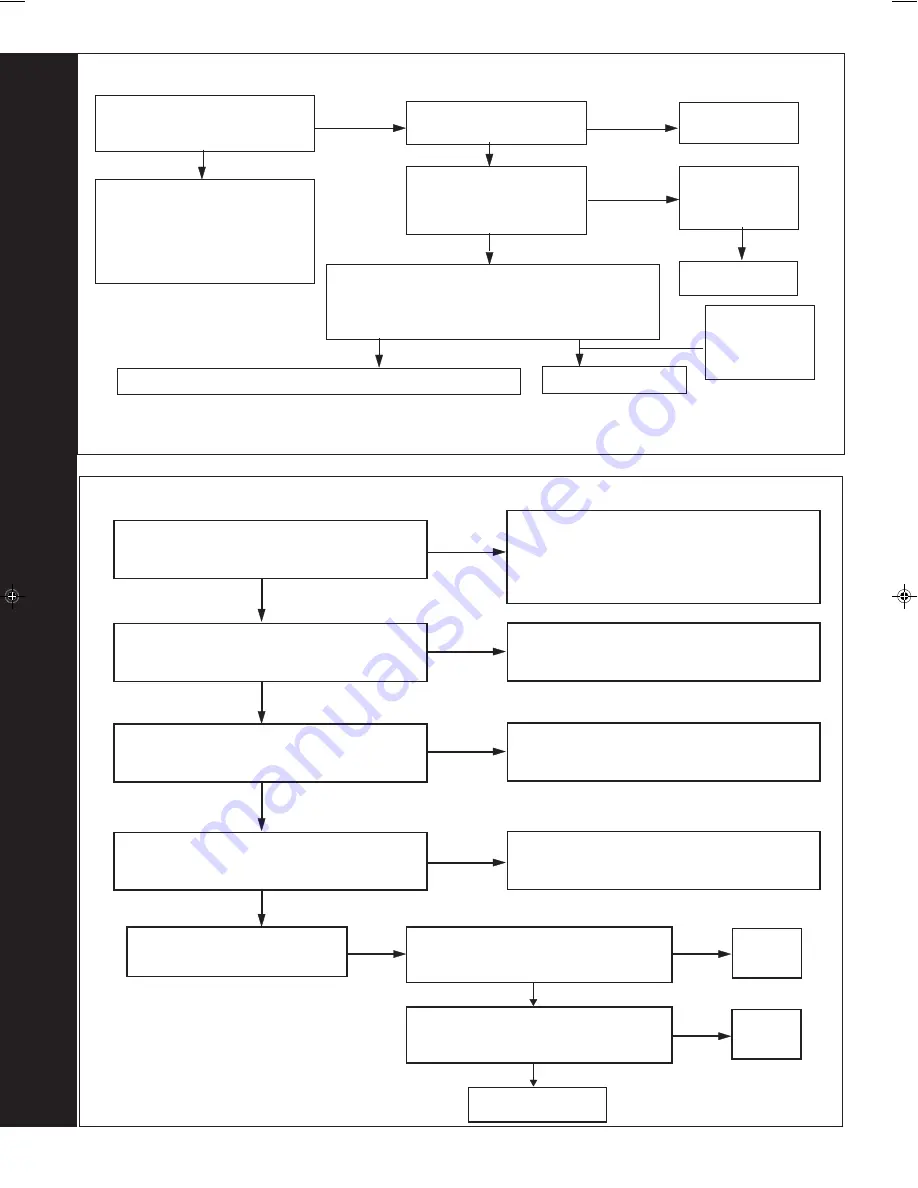
97 L.....F....... (FLAME DETECTION)

Check the ignition electrode and associated  harness

for:      continuity, visual condition

position

 (Refer to Frame 69).

Are these functioning correctly ?

Check gas valve

wiring for

continuity

YES

Check the detection electrode and

associated harness for:

continuity, visual condition, position

(

Refer to Frame 70

).

Replace if necessary.

If the boiler reset button is

pressed does the boiler ignite

for a short time then extinguish?

Is 200V DC supply

available at the gas valve ?

(see Note)

NO

YES

YES

Is 17mbar gas pressure

available at the boiler inlet ?

Replace PCB

Check gas supply

and rectify fault

Replace ignition electrode and associated harness as necessary

NO

Replace gas valve

YES

NO

NO

98 L.....E

or

H.....E...... (BOARD ERROR)

Check for an excess voltage between neutral

and earth. Is the value below 50V?

Check earth connection to the boiler. If

value is still in excess of 50V consult a

Qualified  Electrician to check the

household electrical supply & circuitry.

Note.

Due to the wave form of the rectified voltage, the reading will vary depending on the type of meter used to measure the
value (some may measure the possible peak voltage of 339V). In general terms a reading greater than 150V indicate
that the correct voltage is supplied to the gas valve.

Check syphon

and condensate

drain pipework

for blockage

LE ONLY

: Check continuity of OH thermostat.

Is this correct?

Correct wiring or replace thermostat

HE ONLY

: Check earth wire is connected to

detection lead. Is this correct?

Correct wiring or replace detection lead

Check all earths for continuity

Correct connections

Internal fault within the PCB

Press and hold reset button for 2 seconds.

Does boiler operate correctly?

OK

Turn boiler off and wait for 5 seconds. Turn

boiler on. Does boiler operate correctly?

OK

Replace PCB

NO

NO

NO

NO

NO

NO

YES

YES

YES

YES

YES

YES

Summary of Contents for istor HE260

Page 1: ...to the safety and performance specification that we require Do not use reconditioned or copy parts that have not been clearly authorised by Ideal Boilers HE260 HE325 For the very latest copy of litera...

Page 2: ...2 istor system store Installation and Servicing...

Page 3: ...T AMENDMENTS Relevant Installation changes implemented in this book from Mod Level A03 to A04 Jan 2010 Ideal Stelrad Group reserve the right to vary specification without notice Pipework layout change...

Page 4: ...9 MJ m3 935 Btu ft3 nett To obtain the gas consumption at a different calorific value a For l s divide the gross heat input kW by the gross C V of the gas MJ m3 b For ft 3 h divide the gross heat inpu...

Page 5: ...e on the back page Page Burner operating pressure measure and record Central heating flow temp measure and record Central heating return temp measure and record For combination boilers only Scale redu...

Page 6: ...W is drawn off or periodically for a few seconds without any DHW draw off in order to maintain the DHW cylinder in a heated condition When there is a demand for CH the heating system is supplied at th...

Page 7: ...w pressure installation pipes Health Safety Document No 635 The Electricity at Work Regulations 1989 The manufacturer s notes must NOT be taken in any way as overriding statutory obligations IMPORTANT...

Page 8: ...ere the space into which the boiler is going to be installed is less than the length of flue required the flue must be fitted from the outside Front clearance The minimum front clearance when built in...

Page 9: ...ct and safe operation Allowing for the acceptable pressure loss of 1mb across the installation pipework it can be assumed that a minimum permitted operating pressure of 18mb will be delivered to the i...

Page 10: ...ature control over a living area having a heating requirement of at least 0 9kW 3000Btu h of the boiler heat output should be achieved using a room thermostat whilst other rooms are individually contr...

Page 11: ...RAL ist9827 Roof flue kit to a maximum of 7 5m 100mm Concentric flue to maximum flue length of 6m Powered Vertical Flue Kit typical installation maximum 5m primary with 17m secondary For detailed maxi...

Page 12: ...of the system should not exceed 143 litres if not pressurized However if the system is to be pressurized the efficiency of the expansion vessel will be reduced and a larger vessel or smaller system v...

Page 13: ...is safely conveyed to where it is visible but will not cause danger to persons in or about the building G3 Guidance SECTION 3 9 The discharge pipe D1 from the vessel up to and including the tundish is...

Page 14: ...h equates to 5 8m 5 8m is less than the actual length of 7m therefore calculate the next largest size Maximum resistance allowed for a straight length of 28mm pipe D2 from a G1 2 temperature relief va...

Page 15: ...ime scale may be necessary however the use of artificially softened water is NOT permitted 4 Under no circumstances should the boiler be fired before the system has been thoroughly flushed 21 Overheat...

Page 16: ...system store Installation and Servicing INSTALLATION 10 BOILER MODULE ASSEMBLY Exploded View ist9831 3 45 10 9 11 1 14 23 22 2 16 103 7 8 18 12 6 17 20 20 21 27 13 83 61 85 14 34 34A 5 Data badge INST...

Page 17: ...ervicing INSTALLATION 11 TANK MODULE ASSEMBLY Exploded View ti m e P R O G R A M M E R pro g pro g sele ct sele ct 102 106 105 104 105 33 29 15 91 37 74 77 70 84 107 108 101 73 59 56 55 95 93 92 89 67...

Page 18: ...od correctly as marked on the carton 2 Remove the strapping 3 Fold back the top flaps to gain access to the instructions the pre piping frame and cardboard template 4 Remove the instructions and read...

Page 19: ...1 The PRV pressure reducing valve provided in the hardware pack MUST be fitted in a convenient point on the mains cold inlet to the appliance Once fitted a pressure balanced cold feed to mixer taps a...

Page 20: ...ional gas supply information refer to Gas Supply on page 9 1 Extend a gas supply pipe of not less than 15mm O D copper to the boiler A working gas pressure of 20mbar 8 w g should be available at the b...

Page 21: ...discharge pipe arrangement must comply with G3 Building Regulations This is covered in Frames 6 and 7 18 SAFETY VALVE DRAIN CH A preformed 15mm is supplied strapped to the cylinder module frame This...

Page 22: ...ithin the dwelling IMPORTANT Any external runs must be insulated Excessive external pipe runs should be avoided in order to prevent possible freezing All pipework and fittings in the condensate drain...

Page 23: ...o the packaging base 5 Slide module forward to free it from rear fixings ist9005 Sleeved front panel 21 CONTINUED 3 INTERNAL CONNECTION TO SOILAND VENT STACK Make connection to SVP using a solvent wel...

Page 24: ...r module Note that the CH flow pipe is supplied strapped to the cylinder module frame 2 Slide the tank backward until the stops on the frame are reached 3 Remove the pipe nut protector from the cylind...

Page 25: ...hose to the DHW expansion vessel 26 FLUE SYSTEM This appliance is suitable for use with the following flue system 1 100mm Concentric flue system supplied as standard Refer to Frame 3 2 Powered Vertica...

Page 26: ...dim X 188 dim L 217 5 dim R 342 5 required Up to 595 mm Up to 595 mm Up to 595 mm none Up to 1545 mm Up to 1545 mm Up to 1545 mm Pack D 1 off Up to 2495 mm Up to 2495 mm Up to 2495 mm Pack D 2 off Up...

Page 27: ...ngths greater than 5 5m or any flue length to be outside of the wall increase the off set by 26mm for every additional metre to maintain 1 5 o 3 o inclination 1 ist8792 28 FLUE ASSEMBLY Exploded View...

Page 28: ...go to Frame 34 1 Measure and note wall thickness X Refer to Frame 27 2 Add 145mm 51 2 to dimension X and set telescopic flue length as indicated in drawing 3 Using a 3 5mm drill bit drill one hole in...

Page 29: ...face 2 Locate the flue turret on the top of the boiler ensuring that the turret gasket is in place Also ensure the turret is located concentric with the flue aperture on the boiler top panel Check tha...

Page 30: ...the total flue length from the centre of the boiler outlet to the outside wall 2 Subtract 70mm from this dimension 3 Subtract 950mm for each D pack to be used 4 If the remainder Y is 300mm 525mm this...

Page 31: ...e seal must be made This is achieved by using either Flat roof weather collar or Universal weather collar ACCESSORIES Flue Duct Extension Kits are available for flue lengths extending beyond 1m These...

Page 32: ...ay occur at the termination so where possible terminal positions where this could cause a nuisance should be avoided Minimum dimensions are shown below Terminal Position Minimum Dimension Directly bel...

Page 33: ...stor system store Installation and Servicing INSTALLATION FLUE OUTLET rf8737 rf8738 39 FLUE ARRANGEMENT Note The equivalent flue length resistance of the elbow kits are 90o elbow kit 1m 45o elbow kit...

Page 34: ...tile weather collar 1 nm9429 2 Extension Duct Vertical connector Aluminium sleeve Turret clamp 3 nm8743 X 4 2 Push fit the vertical connector supplied separately into the boiler flue connection and re...

Page 35: ...48 MUST be loose at all times When filling there may be a slight water leak from the vent therefore electrical connections should be protected c Open manual air vent above the diverter valve and blee...

Page 36: ...that allows complete isolation of the electrical supply such as a double pole switch having a 3mm 1 8 contact separation in both poles or a plug and socket serving only the boiler and system controls...

Page 37: ...left off for more than a day or so then a frost thermostat should be wired into the system The frost thermostat should be sited in a cold place but where it can sense heat from the system Note If the...

Page 38: ...r Diverter valve Gas valve PUMP Return thermistor DHW Thermistor User control and display ON OFF Switch Service connection Mains supply 230V 50Hz Fan bk y Chassis earth g y ist9894 Control PCB Fused a...

Page 39: ...uding the meter should be inspected and tested for tightness and purged in accordance with the recommendations of BS 6891 In IE refer to IS 813 2002 2 Purge air from the gas installation by approved m...

Page 40: ...boiler does not light after 3 attempts the fault code LF will be displayed Press the select button M and the boiler will repeat its ignition sequence When the burner is established the flame Burner On...

Page 41: ...ump continue to run The LCD display symbol should be then After 15 seconds the burner should relight to supply central heating The LCD display symbols should be 5 Set the central heating external cont...

Page 42: ...useholder pack supplied with this boiler After completing the installation and commissioning of the system the installer should hand over to the householder by the following actions 1 Hand the User In...

Page 43: ...can not be accurately set with water pressure in system 13 Partially open vent on top of heat exchanger and release any trapped air Partially unscrew cap on the air vent on top of diverter valve and...

Page 44: ...SERVICING 52 SAMPLING POINT 53 BOILER FRONT PANEL REMOVAL 1 Remove the 2 securing screws 2 Pull the top panel forward at the top and lift to disengage it from the locating pins 3 Pull the bottom panel...

Page 45: ...1 Ensure the power supply is turned off 2 Disconnect the 14 way in line molex connector 3 Remove the 2 M5 screws securing the panel 4 Lift off the panel from its locating slots 5 Disconnect the DHW th...

Page 46: ...l box to the expansion vesel bracket 4 The control box can now be raised off its mounting slots and dropped to the base plate 5 Access is now available to remove the 4 fixing screws and lift off the b...

Page 47: ...NG THE CONDENSATE S TRAP 58 BURNER REMOVAL AND CLEANING 1 Remove the 6 screws securing the burner the 3 screws at the rear are extended to ease access 2 Lift off the burner from the combustion chamber...

Page 48: ...do the PRV cartridge and remove the assembly from the brass body 1 Remove ignition and flame detection electrodes Refer to Frames 69 70 2 Remove the 3 screws retaining the sump cover and remove 3 Usin...

Page 49: ...ection to the injector housing 5 Remove the retaining screw and pull off the mounting bracket 6 Remove the fan and venturi assembly 7 Remove the 3 retaining screws and remove the venturi assembly noti...

Page 50: ...assemble in reverse order ensuring that the new gas seal supplied is located correctly in the injector housing 11 Check operation of the boiler Refer to Frame 49 1 Refer to Frame 53 54 2 Remove the bo...

Page 51: ...at from the flow return pipe and withdraw it from the controls compartment 3 Disconnect the electrical leads from the thermistor thermostat 4 Re connect the electrical leads and re assemble in reverse...

Page 52: ...his bag should be retained and the discarded insulation should now be placed into it 10 Sweep any dampened particles and place in the plastic bag 11 Fit new insulation piece a Locate and align the ins...

Page 53: ...e the sensing tube from the gas control valve 5 Undo the gas inlet pipe union 6 Undo the union nut on the RHS of the gas control valve 7 Withdraw the valve complete with inlet pipe 8 Fit the new valve...

Page 54: ...d forwards to remove 5 Transfer the drain pipe to the new trap and re assemble in reverse order 6 When re assembling ensure that the trap is full of water 7 Check operation of the boiler Refer to Fram...

Page 55: ...to Frame 53 54 2 Slacken the backnut on the DHW expansion vessel and remove to one side as shown 3 Remove the fixing screw locating the control box bracket 4 Unplug all the electrical wiring from the...

Page 56: ...79 DISPLAY UNIT REPLACEMENT 80 PRESSURE GAUGE REPLACEMENT 1 Refer to Frame 53 54 2 Unclip lower front panel 3 Drain the boiler Refer to Frame 85 4 Unscrew the pressure gauge and discard 5 Fit the new...

Page 57: ...of screws in support plate and that tabs on the pump and valve housings engage in slots 9 Reconnect the discharge pipe 10 Check operation of the boiler Refer to Frame 49 82 DHW CYLINDER RELIEF VALVE R...

Page 58: ...elease the electrical connections from the spark generator 7 Remove the M5 nut retaining the flue casting spring clip and remove the spring clip 8 Undo the 2 M5 x 10 flue spring clip retaining bracket...

Page 59: ...oiler 86 DRAINING THE CYLINDER 1 Refer to Frame 53 2 Close the DHW isolating valves on the piping frame 3 Attach a length of hose to the drain point and open the drain valve 4 After replacing any comp...

Page 60: ...head and reconnect the electrical lead 6 Refill and check the operation of the boiler 88 PUMP REPLACEMENT 1 Refer to Frame 53 54 2 Drain the boiler Refer Frame 85 3 Disconnect the electrical lead from...

Page 61: ...ration of the boiler Refer to Frame 49 Note If preferred and for convenience a new expansion vessel may be installed elsewhere in the heating system providing it ensures equivalent system protection 9...

Page 62: ...ons 5 Check the DHW delivery temperature and set to the customer requirements ist9878 ist9877 1 Refer to Frames 53 54 2 Remove the old seal from the casing and thoroughly clean the casing surfaces 3 F...

Page 63: ...ing a suitable tool undo the push fit connections from the flow and return pipes of the boiler removing the pump assembly and the diverter valve assembly 16 Remove the fan venturi assembly and place o...

Page 64: ...of the boiler Refer to Frame 49 94 HEAT ENGINE REPLACEMENT continued ist9880 5 6 2 7 Note The replacement immersion heater must be fitted with a thermal cut out 1 Refer to Frame 53 54 2 Remove the DHW...

Page 65: ...F GO TO FRAME 97 L E GO TO FRAME 98 L A GO TO FRAME 99 L 8 GO TO FRAME 100 H 1 GO TO FRAME 101 H 2 GO TO FRAME 102 H 3 GO TO FRAME 103 H 4 GO TO FRAME 104 H F GO TO FRAME 105 In order to assist fault...

Page 66: ...cess voltage between neutral and earth Is the value below 50V Check earth connection to the boiler If value is still in excess of 50V consult a Qualified Electrician to check the household electrical...

Page 67: ...the boiler reset button when the system is cold Replace the system pump Set CH control knob to maximum If the overheat trips again measure the flow temp Over 90 o C Check control thermistor Refer to...

Page 68: ...100 Ohms Remove the boiler return thermistor from the CH return pipe Are the thermistor values correct Replace the thermistor NO YES Replace PCB Check and replace wiring as necessary NO YES Is there c...

Page 69: ...0 Ohms At 85 o C expect 1 000 1 100 Ohms Are thermistor values correct Replace PCB Replace thermistor Fill and vent the system and open all isolating valves YES Check resistance using a suitable multi...

Page 70: ...07 664 Ignition electrode 1 175 406 23 H07 665 Flame detection electrode 1 173 529 27 E67 511 Condensate S trap 1 170 926 29 H07 670 itime programmer user control 1 174 487 30 H07 671 PCB primary cont...

Page 71: ...71 istor system store Installation and Servicing SHORT LIST OF PARTS 107 SHORT PARTS LIST ist9881 38 16 22 10 7 12 14 20 21 82 27 83 90 91 34 101 103 44 85 81 29 33 31 23 97 8 30 92 34A...

Page 72: ...72 istor system store Installation and Servicing SHORT LIST OF PARTS 108BOILER CASING ASSEMBLY 109BURNER ASSEMBLY 1 Sealing panel with screws 7 Burner assembly with screws and gasket Ecl 1598...

Page 73: ...73 istor system store Installation and Servicing...

Page 74: ......

Page 75: ...approved inspector LABC will record the data and will issue a certificate of compliance If you notify via Gas Safe Register they will then notify the relevant Local Authority Building Control LABC sc...

Page 76: ...Gas Safe Register ID Number...

Page 77: ...ister ID Number Gas Safe Register ID Number Gas Safe Register ID Number Gas Safe Register ID Number Gas Safe Register ID Number Gas Safe Register ID Number Gas Safe Register ID Number Gas Safe Registe...

Page 78: ...78 istor system store Installation and Servicing...

Page 79: ...79 istor system store Installation and Servicing...

Page 80: ...cification without notice The Ideal Boilers Technical Training Centre offers a series of first class training courses for domestic commercial and industrial heating installers engineers and system spe...

Reviews: