37
Minimiser
-
Installation
SERVICING
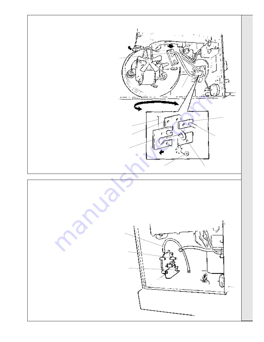
70 FAN UNIT REPLACEMENT
71 PRESSURE SWITCH REPLACEMENT
Refer also to Frame 10 - 'Boiler exploded view'.
1.
Refer to Frame 58.
2.
Remove the fan unit - refer to Frame 53.
3.
Disconnect the pressure sensing pipe from the
switch, noting its position - tapping P1(+).
4.
Disconnect the electrical leads from the switch,
noting their position.
Connections are made to
terminals 1 and 3.
5.
Undo the securing screw and withdraw the
switch.
6.
Fit the new switch in reverse order
7.
Check the operation of the new switch - refer
to Frame 51.
3
4
5
SER
VICING
4
3
(a)
Manifold
block
Refer also to Frame 10 - 'Boiler exploded view'.
1.
Refer to Frame 58.
2.
Disconnect the electrical leads from the fan.
3.
Disconnect the pressure sensing pipe from
the fan.
a.
Undo the 2 screws securing the pipe to
the fan.
b.
Undo the 2 screws securing the pipe
clamping plate to the manifold block.
c.
Withdraw the clamping plate.
d.
Withdraw the pipe from the boiler.
4.
Press the retaining bracket lever upward and
rotate the fan body to the right to disengage
the fan scroll from the bracket. Continue
rotating to disengage the bayonet fixing on the
fan outlet.
5.
Withdraw the fan.
Note.
Always take care when handling the fan
in order to preserve the balance of the
impeller.
6.
Fit the new fan in reverse order, ensuring that:
a.
The O ring seal is correctly refitted.
b.
The sensing pipe clamping plate is
correctly refitted.
7.
Check the operation of the new fan.
(c)
(d)
Clamping
plate
Gasket
Fan pressure
sensing pipe
(b)
Burner pressure sensing pipe


