29
Minimiser
-
Installation
SERVICING
50 SERVICING SCHEDULE
52 BOILER SEALING PANEL REMOVAL
7.
Clean the heat exchanger.
Note.
This must be done with the heat exchanger and
deposits in a dry condition - refer to Frame 55.
8.
Check the main injector for blockage or damage.
9.
Check that the flue terminal is unobstructed and that the
flue system is sealed correctly.
The servicing procedures are covered more fully in Frames
51 to 57 and MUST be carried out in sequence.
WARNING.
Always turn off the gas supply at the gas service
cock, and switch off and disconnect the electricity supply to
the appliance before servicing.
IMPORTANT.
After completing the servicing or exchange of
components always test for gas soundness and carry out
functional checks as appropriate.
Note.
In order to carry out either servicing or replacement of
components the boiler front panel and sealing panel must be
removed - refer to Frames 12 and 52.
IMPORTANT.
When work is complete the sealing panel
MUST be correctly refitted, ensuring that a good seal is made.
DO NOT OPERATE THE BOILER IF THE SEALING PANEL
IS NOT FITTED.
To ensure the continued safe and efficient operation of the
appliance it is recommended that it is checked at regular
intervals and serviced as necessary. The frequency of
servicing will depend upon the installation condition and usage
but should be carried out at least annually. It is the law that
any service work must be carried out by a registered CORGI
installer.
1.
Remove the boiler bottom panel - refer to Frame 59,
step 4.
2.
Light the boiler and carry out a pre-service check, noting
any operational faults.
3.
Check the operation of the pressure switch - refer to Frame
51.
4.
Relight the boiler and operate for at least 20 minutes.
Check the gas consumption.
5.
Connect a suitable gas analyser to the sampling point on
top of the boiler - refer to Frame 51 (optional test).
For correct boiler operation the CO/CO
2
content of the flue
gas should not be greater than 0.004 ratio.
If this is the case, and the gas input is at least 90% of the
nominal, then no further action need be taken. If not,
proceed to step 6.
6.
Clean the main burner.
SER
VICING
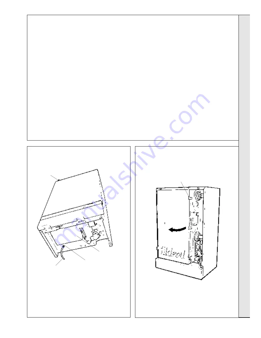
51 PRESSURE SWITCH OPERATION
1.
Connect a flexible tube to the pressure switch tapping,
located at the bottom of the boiler, behind the control box.
Pressure
switch tapping
Control box
Flexible
tube
Flue gas
sampling point
1.
Turn off the gas supply at the gas service cock and
disconnect the electricity supply.
Retaining clips
2.
Remove boiler front panel as described in Frame 12.
3.
Release the three retaining clips on the right hand side
of the panel.
4.
Swing the panel open to the left and disengage it from
the boiler.
2.
With the boiler running, blow gently into the tube. The
burner should shut down and the 'Burner on' neon
extinguish. The fan should continue to run. If this does
not occur replace the pressure switch - refer to Frame 71.
3.
Remove the flexible tube and refit the boiler bottom panel.
Note.
The pressure switch tapping does not have a cap or
sealing screw and MUST be left open to atmosphere.


