53
SERVICING
ESPRIT 2 -
Installation and Servicing
76
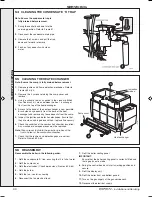
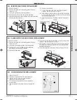
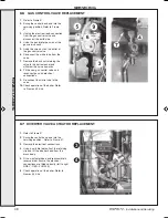
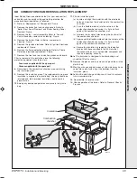
AUTOMATIC AIR VENT REPLACEMENT
HEAT EXCHANGER AIR VENT
1.
Refer to Frame 57.
2.
Remove the boiler front and sealing panels. Refer to
frames 49 & 50.
3.
Drain the boiler. Refer to frame 77.
4.
Remove the turret from the boiler. Refer to frame 26.
5.
Release the silicon tubing from the sample point.
6.
Release the electrical connections from the dry fire
thermistor.
7.
Release the electrical connections from the spark
generator.
8.
Remove the M5 x 10 screw retaining the top flue
manifold casting.
9.
Remove the casting.
10.
Remove the fan from the boiler. Refer to Frame 52.
11.
Remove the burner from the heat exchanger. Refer to
Frame 53.
12.
Unscrew the air vent from its heat exchanger mount
and renew.
13.
Re assemble the boiler in reverse order.
14.
Refill the boiler. Refer to frame 36. Check for leaks
around the new air vent joint.
15.
Check the operation of the boiler. Refer to Frames 45
& 46.
PUMP AIR VENT
1.
Refer to Frame 57.
2.
Swing the control box down into the servicing
position - refer to frame 51
3.
Drain the boiler. Refer to frame 77.
4.
Remove the circulating pump head - refer to frame
80
5.
Locate the automatic air vent head located at the
rear of the of pump chamber plastic housing. If
increased access is required disconnect the 22mm
pipe connection at top a pump chamber and swing
pipe outwards.
6.
The automatic air vent head is retained in the pump
body with a bayonet connection. The air vent head
and float assembly is removed by turning the head
anti-clockwise (viewed from above) and pulling
upwards.
7.
Reassembly is the reverse of the above. Ensure the
air vent head 0 ring seal is in place when refitting.
8.
Refill the boiler. Refer to frame 36. Check for leaks
around the new air vent joint.
9.
Check the operation of the boiler. Refer to Frames 45
& 46.
5
Viewed from back of boiler
SER
VICING
206091-1.pmd
26/05/2010, 16:09
53

