ICS 680GC, Service Manual
Introducing the ICS 680GC - a cutting-edge gadget that simplifies your life! Need a user manual? Look no further! Access the free Quick Start Manual and comprehensive guide for the ICS 680GC instantly. Download it hassle-free from our website and unlock the full potential of this incredible product.
Share
Download


Reviews:
No comments
Related manuals for 680GC
814
Brand: ICS Pages: 15

G5000
Brand: Zenoah Pages: 15
FORMULA 60
Brand: Gardena Pages: 15
G5200
Brand: Zenoah Pages: 17
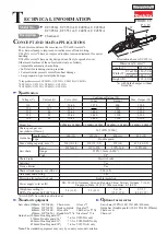
UC3050A
Brand: Makita Pages: 13
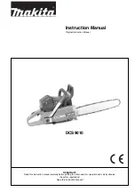
DCS 9010
Brand: Makita Pages: 28
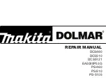
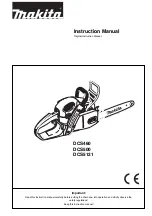
DCS460
Brand: Makita Pages: 32
DCS3500
Brand: Makita Pages: 32
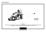
EA6100P
Brand: Makita Pages: 30
DCS460
Brand: Makita Pages: 32
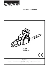
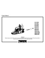
DCS34
Brand: Makita Pages: 28
EA5600F
Brand: Makita Pages: 36
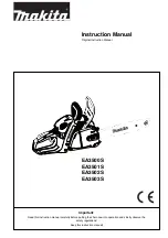
EA3500S
Brand: Makita Pages: 40
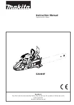
EA3600F
Brand: Makita Pages: 104
UC3530A
Brand: Makita Pages: 136
DCS230T
Brand: Makita Pages: 120
5014B
Brand: Makita Pages: 2
EA3200S
Brand: Makita Pages: 15


