


P 1/ 13
OFFICIAL USE
for ASC & Sales Shop
Model No.
Description
PRODUCT
C
ONCEPT AND MAIN APPLICATIONS
S
pecification
Continuous Rating (W)
Voltage (V)
Cycle (Hz)
Input
Output
Max. Output (W)
110
120
220
230
240
15
14.5
8.6
9.2
8.8
50-60
50-60
50-60
50-60
50-60
1,570
1,800
2,000
2,000
800
900
1,000
1,100
1,100
1,500
1,800
2,200
2,200
2,200
Current (A)
UC3050A, UC3550A, UC4050A, UC4550A
UC3051A, UC3551A, UC4051A, UC4551A
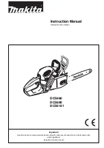
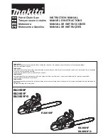
Chain saw
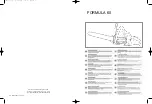
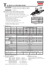
Dimensions
*
4
: mm (")
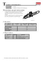
Illustration above is UC3051A.
Width (W)
Height (H)
Length (L)
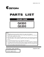
The subject models are the successors of UCxx30A series
*
1
.
The chain oil pump is improved to realize more efficient oiling.
UCxx51A series
*
2
have an improved toolless tension adjustment for easier
handling.
UCxx50A series
*
3
have newly designed nut-fix style sprocket cover.
Other main features of the subject models are as follows;
• Adjustable automatic chain oiling
• Soft start for reducing start-up reaction
• Current limiter protects motor from heat damage
• Large separate-type metal spike bumper
S
tandard equipment
Saw chain
Pitch
Chain brake
Electric brake
Soft start
Yes
Torque limiter
Yes
Chain oil tank capacity: mL (US oz)
Chain speed per sec.:
m/s (m/min.)[ft/min.]
length: mm (")
Type
Double guard
Automatic chain oiling
Protection from electric shock
Power supply cord: m (ft)
Model No.
UC3050A/ UC3051A UC3550A/ UC3551A UC4050A/ UC4051A UC4550A/ UC4551A
14.5 (870) [2,900]
UK: 10 (32.8)/ Germany, Sweden, Reunion, China, Taiwan, Vietnam: 5 (16.4)/
Singapore, India: 2.5 (8.2)/ Other countries: 0.3 (0.98)
5.6/ 5.6
(12.2/ 12.3)
5.5 (12.1)
5.4 (11.9)
5.7/ 5.7
(12.4/ 12.5)
3/8"
200 (6.8)
Yes
Double insulation
Max. cutting capacity: mm (")
Type
91PX-52E
91PX-62E
91PX-56E
91PX-46E
350 (14)
450 (18)
400 (16)
300 (12)
320 (12-5/8)
415 (16-3/8)
355 (14)
260 (10-1/4)
Saw chain (300mm: 91PX-46E,
350mm: 91PX-52E,
400mm: 91PX-56E,
450mm: 91PX-62E)
Guide bar (300mm: Double guard 12",
350mm: Double guard 14",
400mm: Double guard 16",
450mm: Double guard 18")
O
ptional accessories
Saw chain (91PX) (300/ 350/ 400/ 450mm)
Guide bar (Double guard) (300/ 350/ 400/ 450mm)
Chain cover
Chain oil
*
6
: for UC3050A only
*
7
: for UC4050AKX only
*
8
: for UC3551AK only
Weight according to
EPTA-Procedure 01/2003
*
5
: kg
*
4
:
with Spike bumper, without
Guide bar
*
5
:
with 91PX Saw chain and Guide bar
Note:
The standard equipment may vary by country or model variation.
*
1
the predecessors of UC3030A, UC3530A, UC4030A, UC4530A
*
2
UC3051A, UC3551A, UC4051A, UC4551A
*
3
UC3050A, UC3550A, UC4050A, UC4550A
Chain cover
Hook complete
Wrench
*
6
Round file
*
7
,
*
8
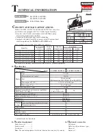
505 (19-7/8)
196 (7-3/4)
220 (8-5/8)
200 (7-7/8)
UCxx50A
UCxx51A
T
ECHNICAL INFORMATION
Gauge
91PX: 1.3mm (0.050")
W
L
H
Gloves
*
7
Goggles
*
7
Chain oil set
*
7,
*
8
Steel case
*
7,
*
8
Guide bar