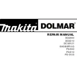
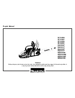
Makita DCS460, Repair Manual
The Makita DCS460, a powerful and efficient chainsaw, enables you to tackle any cutting task with ease. To ensure you get the most out of this exceptional tool, don't forget to download the comprehensive Instruction Manual from manualshive.com, completely free. Unlock its full potential and enhance your cutting experience!
Share
Download


Reviews:
No comments
Related manuals for DCS460
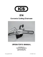
814
Brand: ICS Pages: 15
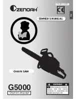
G5000
Brand: Zenoah Pages: 15
FORMULA 60
Brand: Gardena Pages: 15
G5200
Brand: Zenoah Pages: 17
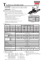
UC3050A
Brand: Makita Pages: 13
DCS 9010
Brand: Makita Pages: 28
DCS3500
Brand: Makita Pages: 32
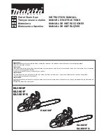
EA6100P
Brand: Makita Pages: 30
DCS460
Brand: Makita Pages: 32
DCS34
Brand: Makita Pages: 28
EA5600F
Brand: Makita Pages: 36
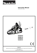
EA3500S
Brand: Makita Pages: 40
EA3600F
Brand: Makita Pages: 104
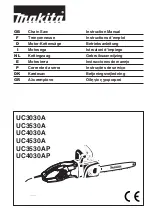
UC3530A
Brand: Makita Pages: 136
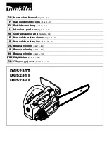
DCS230T
Brand: Makita Pages: 120
5014B
Brand: Makita Pages: 2
EA3200S
Brand: Makita Pages: 15
DCS 6400
Brand: Makita Pages: 32


