background image

ICP DAS PMC/PMD Series User Manual 


155 


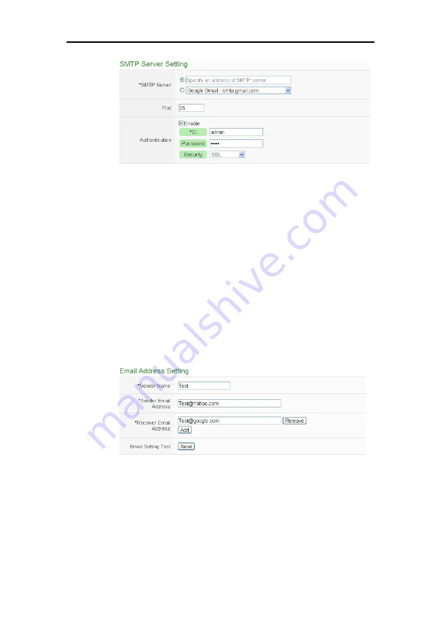
Figure10-3 :


Email setting page(SMTP Server) 


iv


Input the Port number, the default port number is set as 25. 

v


If  the  SMTP  server  requires  account  and  password  validation,  please 

select  the  “Enable”  checkbox,  and  continue  steps  vi~viii  to  login  into 

the  SMTP  server.  If  the  SMTP  server  doesn’t  need  account  and 

password validation, uncheck the “Enable” checkbox and go directly to 

step ix. 

vi


Enter the SMTP server login ID in the “Login ID” field. 

vii


Enter the SMTP server password in the “Password” field. 

viii


In the  “Security” field, select the security setting to be “No Security”, 
“TLS”, or “SSL” from the dropdown list. 

ix


After  complete  SMTP  server  setting,  continue  to  input  Email  address 

setting. In the “Sender Name” field, input the name of the sender. The 

Email Address Setting page is shown as below: 


Figure10-4 :


Email setting page(Email Address) 


x


Enter the sender’s email address in the “Sender Email Address” field. 

xi


In  the  “Receiver  Email  Address”  section,  click  on  “Add”  to  add  the 
receiver’s email address. At least one email address has to be entered. 

xii


To verify whether your email setting is correct to send the Email, click 
“Send” in the “Email Setting Test” section, then PMC/PMD will send a 

test Email to the receiver’s email address. 

Summary of Contents for PMC series

Page 1: ...ICP DAS PMC PMD Power Meter Concentrator Series User Manual Version 3 1 8...

Page 2: ...umed by ICP DAS Inc LTD for its use or for any infringements of patents or other rights of third parties resulting from its use Copyright and Trademark Information Copyright 2017 by ICP DAS Inc LTD Al...

Page 3: ...2 Power Meter Statistics Information Overview 19 5 1 3 Other Information 20 5 1 4 I O Information 20 5 2 Power Data Information 21 5 2 1 Overview 21 5 2 2 Group Overview 22 5 3 Realtime Chart 23 5 3 1...

Page 4: ...e 75 7 Power Meter I O Module Setting 78 7 1 Power Meter Setting 79 7 1 1 Scan to add Modbus RTU Power Meters 80 7 1 2 Add Modbus RTU Power Meter Manually 81 7 1 3 Add Modbus TCP Power Meter Manually...

Page 5: ...g 137 9 1 Microsoft Azure Setting 137 9 2 IBM Bluemix Setting 142 9 3 MQTT Setting 144 9 3 1 Broker Setting 144 9 3 2 Topic Import Export Setting 150 10 Advanced Setting 153 10 1 Email Setting 153 10...

Page 6: ...11 2 10 SNMP Trap 215 11 2 11 LINE Notify 215 11 2 12 Data Logger 216 11 2 13 Rule Status 216 11 2 14 Internal Register 217 Appendix I Modbus Address Table 219 Appendix II Reset to Factory Default Se...

Page 7: ...4 14 Power data Overview page 13 Figure4 15 Select the classification of Power data 13 Figure4 16 Display power data of the selected classification 14 Figure5 1 Information display options on Main Pag...

Page 8: ...time 39 Figure5 34 PUE information History 1 40 Figure5 35 PUE information History 2 40 Figure5 36 I O Information login as Administrator 41 Figure5 37 I O Information login as General User 41 Figure5...

Page 9: ...Figure6 25 Other setting page 68 Figure6 26 Power Meter Group Setting 69 Figure6 27 Group and Subgroup Viewing 70 Figure6 28 Group Setting 70 Figure6 29 Subgroup Setting 70 Figure6 30 Subgroup Setting...

Page 10: ...dband Operation a numerical value 95 Figure7 25 XW Board AO attribute setting page 96 Figure7 26 I O Module Setting Page 97 Figure7 27 The Scan button to search M 7000 DL module 98 Figure7 28 Set up t...

Page 11: ...of IoT Platform 140 Figure9 4 Microsoft Azure Subscribe Topic setting page 140 Figure9 5 IBM Bluemix Setting page 142 Figure9 6 IBM Bluemix Subscribe Message setting page 143 Figure9 7 MQTT Setting Pa...

Page 12: ...Figure10 31 Timer setting page Internal Register 175 Figure10 32 Schedule setting page 175 Figure10 33 Calendar mode of Schedule setting 176 Figure10 34 Repeat mode of Schedule setting 177 Figure10 3...

Page 13: ...etting page 205 Figure11 28 Coil Output action setting page 208 Figure11 29 Holding Register action setting page 208 Figure11 30 Power Meter Relay Action setting page 209 Figure11 31 Microsoft Azure F...

Page 14: ...MC PMD series products are including following models PMC 5231 Industrial IoT Power Meter Concentrator without local display PMC 5231M 3GWA 3G Industrial IoT Power Meter Concentrator without local dis...

Page 15: ...t power demand management and alarm notification functions and is able to perform load shedding of the devices if required and enables real time monitoring and control of the power consumption of the...

Page 16: ...t solution Built in Web Server allows to set up the parameters of the power meters and view power data via browsers Power Data Display Support ICP DAS Modbus TCP RTU power meters Display real time or...

Page 17: ...gs and encoded function for the content to avoid unauthorized access to the system PMC 5231M 4GE 4GC PMC 5231M 3GWA supports 4G 3G Wireless data communication With the 4G 3G SIM card it can send the d...

Page 18: ...dmin to login into the page 5 After login in PMC PMD web page go to System Setting Network Setting modify the network setting to fit current network environment More detailed setting information pleas...

Page 19: ...tion and I O modules information it also allows performing Logic rule edition Only one administrator is allowed to login into the system at the same time General User Default password User General use...

Page 20: ...e displayed and will automatically read settings of the PMC PMD to the webpage Figure4 1 PMC PMD Main Page PMC PMD main page could be divided into 3 areas A System function area B Sub function area C...

Page 21: ...bar When login as a general user the setting functions in Rules management toolbar and System function toolbar will be locked and only allows viewing the power meter data the I O module data and Real...

Page 22: ...to click on Save button to save the new settings cleared settings to the PMC PMD Please note once the settings are cleared and save to the PMC PMD the settings will be cleared permanently Figure4 6 Co...

Page 23: ...rm to logout The settings are not saved Please note 1 All the edited settings on the webpage have to be saved to PMC PMD to make all settings take effect before click on button the settings will only...

Page 24: ...he list Figure4 12 Real time information list 4 1 3 System function toolbar According to the level of login permission the System function toolbar will be different If login as an administrator all pa...

Page 25: ...d to show the current function path Figure4 13 Current function path 4 3 Data review System setting area Data review System setting area allows to set system parameters and data review of PMC PMD the...

Page 26: ...mediately The power data classification includes the following options V Voltage I Current kW Real Power kvar Reactive Power kVA Apparent Power PF Power Factor kWh kvarh kVAh Daily Accumulated Electri...

Page 27: ...er Manual 14 Figure4 16 Display power data of the selected classification Connection Status will reveal the connection status between the power meter and PMC PMD the graphic indicators are as follow O...

Page 28: ...1 Power Meter Information Power Meter Information page displays detailed power data information including Power Meter Information Overview and Power Meter Statistics Information Overview 5 1 1 Power M...

Page 29: ...s they are connected to the PMC PMD Currently PMC PMD supports connecting to power meter via Modbus RTU Figure 5 3 or Modbus TCP Figure 5 4 If the power meter is connected via Modbus RTU it will displ...

Page 30: ...tion of the selected Power Meter For 3 phase power meter it will display real time information of Phase A Phase B and Phase C Figure 5 5 For single phase power meter it will display real time informat...

Page 31: ...3112 Reset Accumulated Value of the Power Meter When login as the Administrator it allows to click on Reset to reset the value of kWh kvarh and kVAh to be 0 if required Please Note After performing t...

Page 32: ...Monthly Maximum Demand etc In the Statistics Information section the Daily Monthly Yearly Accumulated Electricity and Daily Monthly Yearly Carbon Emissions for each loop will be displayed Figure5 8 P...

Page 33: ...ameters of the power meter Figure5 9 Power Meter Other Information Page 5 1 4 I O Information In the I O information page the I O status of the power meter will be listed When login as the Administrat...

Page 34: ...on from the dropdown list of the Data Classification field it will list the requested data from various power meters for easy comparison The page refreshes every 20 seconds the user could also click R...

Page 35: ...roup Overview Power Data Information group overview mode allows display of power data of pre set group of power meters please refer to 6 8 Power Meter Group Setting The page refreshes every 20 seconds...

Page 36: ...power data will be varied according to the selected power data classification 5 3 Realtime Chart Realtime Chart allows display of power information of the power meter in real time trend and pie chart...

Page 37: ...choose desired power data classification to view the corresponding Realtime Chart The chart refreshes every 5 seconds Figure5 15 Realtime Chart Power Meter Mode There are three function icons on the u...

Page 38: ...responding subgroups will be listed If the selected Group contains no subgroup or the subgroup doesn t setup any loop phase of the power meter the inquiry operation will not be able to perform Data Cl...

Page 39: ...user could click and drag on the chart and move forward or backward to show desired time zone Click to resume the update of the chart To view the data on a specific marker move the mouse over the mark...

Page 40: ...Power Meter List if no power meter is connected the inquiry operation will not be able to perform Data Classification Data Classification allows to inquire various power data options including V Volta...

Page 41: ...isplayed Figure5 18 Historical Data Chart for power data On the upper left of the Historical Chart there are 4 function icons Set the Historical Chart to be default status Zoom in the Y axis of the Hi...

Page 42: ...ous page Go to specific page Go to next page Go to last page 5 5 Historical Data Report The Historical Data Report allows display of the power data report of desired power meter specify the power mete...

Page 43: ...t Type Allow to inquire Daily Report Weekly Report Monthly Report or Annual Report options Report Date The dates that are available for data retrieval will be displayed Please note if no log file is a...

Page 44: ...ICP DAS PMC PMD Series User Manual 31 Figure5 21 Daily Report for PM 3133 Figure5 22 Daily Report for PM 3114 Figure5 23 Total Accu Electricity report for Power Meters Group...

Page 45: ...under this section and then select the loop s phase s to be inquired the corresponding Energy Usage Analysis will be displayed in Trend chart format Figure5 24 Energy Usage Analysis by Trend Function...

Page 46: ...User defined In user defined mode all power meters connected to the PMC PMD will be listed If no power meter is connected the user will not be able to perform inquiry operation The minimum loop phase...

Page 47: ...e Energy Usage Analysis by Trend Chart to be default status Zoom in the Y axis of the Energy Usage Analysis by Trend Chart Zoom out the Y axis of the Energy Usage Analysis by Trend Chart Hide the mark...

Page 48: ...Data Classification includes V voltage I current PF power factor Energy Usage KWh and Maximum Demand Chart Type Provides Yearly Chart Quarterly Chart and Monthly Chart Date Select the date range to b...

Page 49: ...sification and the time range under this section and then select the loop s phase s to be inquired the corresponding Energy Usage Breakdown by Circuit Group will be displayed in category pie chart to...

Page 50: ...Figure5 31 Inquiry by Group Mode User defined In user defined mode all power meters connected to the PMC PMD will be listed If no power meter is connected the user will not be able to perform inquiry...

Page 51: ...ICP DAS PMC PMD Series User Manual 38 Figure5 32 Energy Usage Breakdown by Circuit Group Chart...

Page 52: ...ich are calculated by Total Facility Energy and IT Equipment Energy preset by users The page refreshes every 20 seconds the user could also click Refresh button to refresh the data immediately Figure5...

Page 53: ...es Daily Chart and Monthly Chart Date The dates which are available for PUE data retrieval will be displayed Please note if no log file is available the inquiry operation will not be performed Click o...

Page 54: ...MD If login as the Administrator it allows to modify the values of Internal Registers or output values of the DO AO channels Figure 5 36 If login as a general user they are allowed to view the values...

Page 55: ...There are three function icons on the upper area of the I O Realtime Chart The icon allows to pause the update of the chart only the data within the 25 minutes will be displayed The user could click a...

Page 56: ...then click on Inquiry button it will show the chart The interface is shown as below User also can click the Download CSV button to download the csv file of the Data Logger for the specify date Using P...

Page 57: ...le to perform Click on Inquiry to display the channel data historical statistic chart Figure 5 40 of the selected date If the selected date does not contain the file or exceeds the date of the file st...

Page 58: ...g information The PMC PMD failed to read data of the power meter s Change the network settings on the PMC PMD Save settings to the PMC PMD Change the system time setting Reset accumulated power data o...

Page 59: ...e Information The graphic indicator on the right side of the No will reveal the connection status of the module the graphic indicators are as follow Online Offline Connecting 5 13 Modbus Table Informa...

Page 60: ...dule name or information of Module Name will be listed Click on Inquiry to display the Modbus table information of the selected module The users can click on the Print button to print this Modbus addr...

Page 61: ...ICP DAS PMC PMD Series User Manual 48 Figure5 46 Power Meter UID Information Page Users can click Export button to export the UID information as CSV file...

Page 62: ...ing Security Setting I O Interface Setting Power Meter Group Setting and Other Setting When you get into the System Setting page the system settings information of this PMC PMD will be displayed as sh...

Page 63: ...will read and display current time of the PMC PMD To modify the system time of PMC PMD set up the date and time on the Time Setting page section and then click save to complete the settings The user...

Page 64: ...to restore the default Time Server settings iii The default Port number setting is 123 currently it is not allowed to be modified iv In the Sync Interval field select the time interval to specify how...

Page 65: ...etting allows making a change to network configuration web server port or Modbus settings on the PMC PMD The following figure illustrates the configuration interface Please Note PMC 52xx PMD series on...

Page 66: ...the Connection mode field please select the connection mode as Obtain an IP address automatically DHCP or Specify an IP address then modify IP Mask Gateway DNS Server IP configuration After all setti...

Page 67: ...4GE or 4GC PMC 5231M 3GWA to complete the 4G 3G Network connection automatically when power on PMC User can click the Connection Testing button to test the 4G 3G Network connection status between the...

Page 68: ...dropdown list Currently system provides 4 service providers for selection as ChangeIP com FreeDNS DynDNS and No IP User can also select Disable to disable the service iii If user selects No IP ChangeI...

Page 69: ...lly based on the new setting If the connection mode is Obtain an IP address automatically DHCP the system may fail to re connect to the web page because the IP address is changed Please use PMC Utilit...

Page 70: ...te VPN server Please click Test or Save button to test or save the settings The description of these two buttons are as below Test button The system will test the VPN connection settings If the connec...

Page 71: ...of LAN1 or LAN2 to login the system 2 When the user is using the VPN IP address to login the system and save the VPN settings the system will logout the user and redirect the webpage to the new VPN I...

Page 72: ...ICP DAS PMC PMD Series User Manual 59 Figure6 11 Security setting interface of VPN function...

Page 73: ...SNMP Setting Page Please follow the steps below for the SNMP Settings i In the Version field select the SNMP version that you want to use Currently PMC PMD supports SNMP V2c and V1 protocol ii In the...

Page 74: ...er List i Set up IP Address or domain name of the SNMP Manager that you want to add Please set up the Address appropriately if the settings are not the same as the settings of the SNMP Manager the int...

Page 75: ...commands indicating that it will allow accepting the Read Write commands from ANY SNMP Manager iii After completing the IP address and working model setting please click button to add the SNMP Manager...

Page 76: ...vides two passwords sets one for Administrator the other for Guest The default password for Administrator is Admin and User for Guest The user can modify the password in the Password Setting section t...

Page 77: ...is section it allows to enable or disable the FTP Server function on the PMC PMD side The user could connect to PMC PMD FTP Server via FTP software to remotely retrieve event log or data record file T...

Page 78: ...on settings on COM Port or LAN of PMC PMD The setting interface is shown as below Using PMC 5151 as an example Figure6 21 I O Interface Setting Page The I O interface functions for PMC PMD are as belo...

Page 79: ...N LAN connection is by default set for Modbus TCP Slave to connect HMI or SCADA It can also be set for Modbus TCP Mater to connect Modbus TCP devices PMD 4201 COM1 COM2 RS 485 Reserved for Modbus RTU...

Page 80: ...e of PMC PMD and Modbus RTU slave device have to be set the same ii In the Parity and Stop bits fields set up the Parity and Stop bits The Parity and Stop bits of PMC PMD and Modbus RTU slave device h...

Page 81: ...via LAN Figure6 24 I O Function setting about LAN The LAN function on PMC PMD is by default set for Modbus TCP Slave to connect HMI or SCADA User can also select the Modbus TCP Master Checkbox to ena...

Page 82: ...g In this section it allows to set Carbon Footprint Setting Please input the Carbon Footprint factor based on the Carbon Footprint factors for countries worldwide that the International Energy Agency...

Page 83: ...27 Group and Subgroup Viewing 6 8 2 Group and Subgroup Setting i Click the Set up button of group or subgroup to open the setting window Figure6 28 Group Setting Figure6 29 Subgroup Setting ii Input...

Page 84: ...the Group Subgroup Setting page Please select the group subgroup first and click on the function button to perform the configurations Change Name Click the radio button in front of the group and clic...

Page 85: ...ttings of the old group will be copied to this newly added group Remove Click the radio button in front of the group and click on Remove to remove the selected group Close Click the Close button to re...

Page 86: ...PMC PMD Series User Manual 73 Figure6 33 Choose Loops Phased of Subgroup Figure6 34 Add Loops Phases for Subgroup 6 8 5 Loop Phase of group configuration Figure6 35 Configurations for Loops Phased of...

Page 87: ...e radio button in front of the loop phase name and click on Move Up to move the loop phase to upper order upper index number No Move Down Click the radio button in front of the loop phase and click on...

Page 88: ...ser after the update is completed the PMC PMD doesn t require to reboot Please follow the steps below i Please contact ICP DAS service to obtain the latest version of the PMC PMD firmware file ii Go t...

Page 89: ...to select the new firmware file and click Open Figure6 37 Firmware Update 2 iv Click Update to update the firmware Figure6 38 Firmware Update 3 v Click OK to start the firmware update to cancel the f...

Page 90: ...the update window or perform any system modification or may result in unexpected failures Figure6 40 Firmware Update 5 vii Click OK to complete the update process After the update is completed please...

Page 91: ...nd I O Modules that are connected to the PMC PMD After getting into the setting page the overview page will display current setting of the power meters and I O Modules that are connected to the PMC PM...

Page 92: ...or Modbus RTU and Modbus TCP power meters After all settings are completed click Save button to save the changes Please note 1 PMC PMD provides 2 COM Port RS 485 interface that allows connections to M...

Page 93: ...at are connected to the PMC PMD Figure7 3 The Scan button to search Power Meter iii When the Scan page appears Figure 7 4 input the starting address and the ending address of the Modbus address that a...

Page 94: ...please select the actual device that are connected to PMC PMD After all settings are completed click Save button to save the changes Figure7 6 The Power Meter List after Scan operation Figure7 7 Selec...

Page 95: ...f the setting is not accurate the connection for PMC PMD to the power meter will be failed Figure7 8 Set up the No and Address of the power meter iii Select the Power meter model Figure7 9 Select Modb...

Page 96: ...below i No The Number will be the order that the power data of the Modbus TCP power meter being stored in the PMC PMD Modbus Table The range is 1 16 ii Network Set up the settings of IP Port and NetID...

Page 97: ...er Meter List Interface After the Modbus RTU TCP Power Meters are added to the power meter list via auto scan or manual work the Modbus RTU TCP Power Meters will be listed as below Figure7 14 Power Me...

Page 98: ...r in sequence will be added to the list and the settings of the old power meter will be copied to this newly added power meter Remove Click the radio button in front of the power meter and click on Re...

Page 99: ...ng Timeout The time interval for PMC PMD to send command to the Modbus RTU Power Meter and wait for the response the unit will be ms The setting range will be 1 10000 ms Retry Interval The time interv...

Page 100: ...hase Modbus RTU Power Meter Setting section CT Phase Nickname For user to define nicknames for each CT or phase this nickname will be displayed on the Power Meter Information and Rule Setting pages Fo...

Page 101: ...ame For user to define nicknames for each power meter this nickname will be displayed on the Power Meter Information and Rule Setting pages Description The Description field provides a space for the u...

Page 102: ...y send command again when PMC PMD sends command to the Modbus TCP Power Meter and get no response The unit will be second the setting range will be 3 65535 seconds Main Power Meter When the Set as mai...

Page 103: ...that are connected to the PMC 5151 PMC 5231 from the drop down list and click Setting a window for setting up the parameters of XW Board XV Board and its I O channel will appear The setting for the m...

Page 104: ...r of this DI channel will not function Counter Initial Value Set the initial value of the counter in the Counter Initial Value field This counter will start counting from the initial count value The d...

Page 105: ...own list Pulse Output If the Pulse Output is selected it will allow this DO channel to perform pulse output and form a periodic pulse cycle In Pulse Output mode the selected DO channel will generate a...

Page 106: ...ted click OK button to return to XW Board XV Board Setting page 7 2 3 XW Board XV Board AI Channel Settings The XW Board XV Board AI Channel Setting page is shown as follow using PMC 5151 XW310C as an...

Page 107: ...three operation styles for AI Deadband The AI Channel setting in following examples is 0mA 20mA a In the IF Condition when AI or a numerical value Assuming the Deadband value is set to be 2 mA and th...

Page 108: ...Deadband Operation or a numerical value c In the IF Condition when AI a numerical value Assuming the Deadband value is set to be 1 mA and the following statements are defined in the related logic Rule...

Page 109: ...ormation about jumper adjustment on XW310C please refer to Appendix V 7 2 4 XW Board XV Board AO Channel Settings The XW Board XV Board AO Channel Setting page is shown as follow using PMC 5151 XW304...

Page 110: ...ote 1 The 2 COM Port RS 485 interfaces on PMC PMD allows connections to Modbus RTU I O modules 2 The LAN interface on PMC PMD allows connections to Modbus TCP I O modules For more detailed information...

Page 111: ...he starting address and the ending address of the Modbus address that are going to perform scan Click on Scan the system will start to scan the M 7000 DL modules that match the settings previously set...

Page 112: ...f the newly scanted module doesn t match the module previously set on the same address a window will appear Figure 7 31 please select the actual device that are connected to PMC PMD After all settings...

Page 113: ...the settings of the module if the setting is not accurate the connection for PMC PMD to the Modbus RTU module will be failed Figure7 32 Set up the No and Address of the Modbus RTU module iii Select t...

Page 114: ...The number will be the order that the I O channel data of the Modbus TCP module being stored in the PMC PMD Modbus Table The range is 1 16 ii Network Set up the settings of IP Port and NetID appropri...

Page 115: ...k on the function button to perform the operations Setting Click the radio button in front of the Modbus I O module and click on Setting to get into the setting page of the Modbus I O module The setti...

Page 116: ...n The Description field provides a space for the user to make a brief description of this M 7000 DL module Address The address will be the Modbus address of this M 7000 DL module please make sure the...

Page 117: ...unter when power on If the Reset counter when power on is selected for the DI channel the DI channel counter of this M 7000 module will be reset to the default value when the PMC PMD is powered on or...

Page 118: ...ions for advanced function Disable Disable the advanced function Auto OFF When Auto OFF is selected it allows this DO channel to enable Auto OFF function It is required to set up a time interval when...

Page 119: ...et up the Power On value of the DO channels on M 7000 DL modules please use DCON Utility to set the value 2 The DO channels on M 7000 DL modules do not offer Pulse Output function The AI channel setti...

Page 120: ...ed information Scale Please refer to Scale section in the 7 2 3 XW Board XV Board AI Channel Settings for more detailed information After all settings are completed click OK button to save the changes...

Page 121: ...that support Modbus RTU Slave protocol for offering I O interface function Through Modbus RTU protocol it enables to read or write 4 types of Modbus data Coil Output Discrete Input Input Register and...

Page 122: ...it for the response the unit will be ms The setting range will be 1 10000 ms Retry Interval The time interval to wait for PMC PMD to repeatedly send command again when PMC PMD sends command to the Mod...

Page 123: ...eve Data Number After finishing the Start Address setting specify the Data Number it is the number of Coil Output data you would like to retrieve from the Start Address After finishing the Start Addre...

Page 124: ...nd 00303 Figure7 44 Coil Output Setting Example for Modbus RTU Module To modify the starting address or quantity setting please click on the setting block and input the setting Click OK for modificati...

Page 125: ...of the data on the PMC PMD that would be retrieved to the Discrete Input 1x on the Modbus RTU module Data Number After finishing the Start Address setting specify the Data Number it is the number of D...

Page 126: ...2 10303 10304 and 10305 Figure7 46 Discrete Input Setting Example for Modbus RTU Module To modify the starting address or quantity setting please click on the setting block and input the setting Click...

Page 127: ...are as below Data Model PMC PMD offers 4 Data Model selections to match the Modbus RTU Slave module configuration Please refer to the above section The Coil Output Setting of Modbus RTU Module for de...

Page 128: ...2 bit Floating Point the option Inverse Big Endian will appear Enable Inverse Big Endian to receive the data in big endian format correctly After finishing the Start Address Data Number and Type setti...

Page 129: ...ister value in this block by linear transformation The formula is as follow Transformed Value Scale Ratio x Input Register value Offset After the linear transformation the Transformed Value will be sa...

Page 130: ...click OK button to save the changes The Holding Register Setting of Modbus RTU Module The Modbus RTU Slave module Holding Register Setting page is shown as follow Figure7 49 Holding Register Setting P...

Page 131: ...value and transfer it to real value in floating point format this real value could be included in the IF THEN ELSE rule for edition If users select 32 bit Signed Long 32 bit Unsigned Long or 32 bit F...

Page 132: ...block to perform the modification The user could also modify Type Scale Ratio Offset and Deadband on this interface For more detailed information please refer to above section The Input Register Sett...

Page 133: ...Module Setting Page 1 The settings are as below Nickname For user to define nickname for each I O channel this nickname will be displayed on the I O Information and Rule Setting pages Description The...

Page 134: ...e the unit will be ms The setting range will be 1 10000 ms Retry Interval The time interval to wait for PMC PMD to repeatedly send command again when PMC PMD sends command to the Modbus TCP module and...

Page 135: ...log files of these two data loggers are both in CSV format that enables easy integration with the backend database system In addition PMC PMD also provides function to set the Log File Retention Time...

Page 136: ...e Power Data Logger allows recording the power data of the power meters that are connected to the PMC PMD the I O Data Logger allows recording all the data of the I O modules that are connected to the...

Page 137: ...nning of the power data logger file to specify the name of the power data Please note After enable this function the User Defined Data Logger will also add the Column Header at the beginning of the da...

Page 138: ...or user to check the settings in an easy way The figure above shows an example of the encoded strings the variable C2M3ri4352 indicates the V value of PM 3112 Loop 1 on the module 3 connected to COM2...

Page 139: ...ger 2 The data logger files of Power Data Logger and User Defined Data Logger all are saved in the micro SD card If the micro SD card s free space is less than the required space of one day data recor...

Page 140: ...i The user could test if the FTP settings are correct in the Remote FTP Server Setting Test section After clicking Send the system will create a folder on the remote FTP server and will generate a tes...

Page 141: ...th Power Data logger files and I O Data logger files can be upload to remote ICP DAS IoTstar IoT Cloud Management Software The Cloud Upload Setting page is shown as below Figure8 5 Cloud Upload Settin...

Page 142: ...ort Log 01A3851F140000D3_2 3133 7 2013 05 23Rpt csv Monthly Report Log 01A3851F140000D3_2 3133 7 2013 05Rpt csv 01A3851F140000D3_2 3133 7 is the ID of this power meter 01A3851F140000D3 indicates the s...

Page 143: ...date the data is recorded The power meter information file _info txt is used to record the nickname of the power meter and the related information of the PMC PMD which connect to the power meter The U...

Page 144: ...kWh Current demand 15 30 60 mins CT2 Voltage Current kW kvar kVA PF kWh kvarh kVAh Daily tot Electricity kWh Current demand 15 30 60 mins CTN Voltage Current kW kvar kVA PF kWh kvarh kVAh Daily tot E...

Page 145: ...ctricity kWh Current demand 15 30 60 mins Phase B CT23 Voltage Current kW kvar kVA PF kWh kvarh kVAh Daily tot Electricity kWh Current demand 15 30 60 mins Phase C CT24 Voltage Current kW kvar kVA PF...

Page 146: ...tal daily kvar Reserved Field PM 2134 PM 3112 MTCP PM 3114 MTCP Daily Report Index of hour Date Power meter ID CT1 Timing of hourly max kW hourly max kW Hourly total Electricity Average hourly PF Aver...

Page 147: ...ourly max kW hourly total Electricity Average hourly PF Average hourly current Average hourly voltage Average hourly kVA Average hourly kvar CT6 Timing of hourly max kW hourly max kW hourly total Elec...

Page 148: ...max kW daily max kW daily total Electricity Average daily PF Average daily current Average daily voltage Average daily kVA Average daily kvar CT6 Timing of daily max kW daily max kW daily total Electr...

Page 149: ...y the user In addition the system will tag each data log with information such as date time and type of the data etc The log type could be Period Recording that will record the file periodically or Tr...

Page 150: ...nd receive the command message from IoT Cloud Platform to trigger the corresponding actions of PMC 52xx PMD at the field side With the IoT Platform Setting function the PMC 52xx PMD provides it helps...

Page 151: ...having to wait for the long TCP IP timeout iv The value in Periodical Publish Interval field defines the time interval to automatically and periodically send the Publish Messages which are with the P...

Page 152: ...ts a specific channel it means the specific power data or I O channel value of the module will be bound with the Publish Message If user select All channels it mean all power data and I O channel valu...

Page 153: ...sage will be published at periodic time schedule based on the value in Periodical Publish Interval field at Step iv xi After completing all settings of Publish Message please click OK button to add th...

Page 154: ...he corresponding value of the Target and Action variables from the message The value of the variables can be used in the evaluation criteria of IF Condition to trigger THEN ELSE Action for logic opera...

Page 155: ...Enable in the Function Status field to enable the connection to IBM Bluemix IoT Cloud Platform ii In the Organization ID Device Type Device ID and Device Authentication Token fields input the data you...

Page 156: ...emix and reply the connection status to verify the setting is correct or not vi The lower half section on the IBM Bluemix Setting Page is for the Publish Message and Subscribe Message setting User can...

Page 157: ...on x After completing all settings on the IBM Bluemix Setting Page please click Save button to save the settings After downloading the settings to the PMC 52xx PMD the PMC 52xx PMD will initiate the c...

Page 158: ...ge Broker The settings steps are as below i Click the Broker Setting tab on the right top corner of MQTT Setting Page ii Click on Add new MQTT Broker to add the new MQTT Broker After clicking the Add...

Page 159: ...ker or not If the Broker does not require Client ID for the connection this field can be ignored ix If the SSL TLS encryption mechanism is required for the connection between the Broker and the PMC 52...

Page 160: ...tring of the Topic Prefix will be the model name of the PMC 52xx PMD If there are more than one PMC 52xx PMD controllers in a system for MQTT connection please remember to change the Topic Prefix sett...

Page 161: ...the module will be bound with the Publish Message If user select All channels it mean all power data and I O channel values of the module will be added in the Publish Message List If the user click th...

Page 162: ...riation exceeds xxx and Periodical Publish If the When the I O channel data changed and the variation exceeds xxx is selected the system will automatically publish the topic when the power data or I O...

Page 163: ...cribe Topic It allows user to change the value of the Internal Register and the value of the output channel of I O module or power meter by MQTT protocol Please refer to Appendix VII for detailed info...

Page 164: ...of MQTT Topic To use the Topic Import function please prepare a document with the same format as The_nickname_of_Topic Topic message Click the Import Topic button then browse through to select the do...

Page 165: ...ICP DAS PMC PMD Series User Manual 152 The Import of MQTT Topic...

Page 166: ...avoid possible error when performing rule definition IF THEN ELSE please always finish configuration in Advanced Setting before starting to define Rules Avoid unnecessary change in Advanced Setting a...

Page 167: ...own as below Figure10 2 Email setting page Name Description iii In the SMTP Server field enter the IP or the domain name of the SMTP server or select the SMTP server from the dropdown list In the drop...

Page 168: ...ield viii In the Security field select the security setting to be No Security TLS or SSL from the dropdown list ix After complete SMTP server setting continue to input Email address setting In the Sen...

Page 169: ...d information of the Real time variable editor xiv Click on OK to confirm the setting and leave the setting page xv Repeat steps i xv to complete settings of all Emails To modify the settings of a pre...

Page 170: ...orized phone numbers only There are 2 types of SMS commands Retrieve channel data GET The user can retrieve specific channel real time data One SMS Command message can require up to 10 channel data va...

Page 171: ...Remove to remove the phone numbers you want to delete vi Enter the content in the Message field If the Unicode mode is adopted the length of the content cannot exceed 70 characters If the Unicode mode...

Page 172: ...is newly added SMS Alarm xi To remove a pre set SMS Alarm please click the radio button in front of the pre set SMS Alarm and then click Remove xii After you finish all the SMS Alarm selections and se...

Page 173: ...mand in the Command String Editor section In the Command String Editor section select the command type to be GET retrieve real time channel data or SET modify channel data from the dropdown list For G...

Page 174: ...ting for SET Command vii Click on OK to confirm the setting and leave the setting page viii Repeat steps v vii to complete settings of all SMS Command setting The SMS Command and its original correspo...

Page 175: ...r send SMS message DO to PMC 5151 PMC 5151 will set the value of DO0 on XW310C XW Board to be ON after receiving the message ix To modify the settings of a pre set SMS Command please click on the radi...

Page 176: ...re10 12 SNMP Trap Setting Page The settings steps are as below i Input Nickname and Specific ID and then click button to create a new SNMP Trap ii To modify the settings of a pre set SNMP Trap please...

Page 177: ...ace will be shown as below Figure10 14 Channel Data Type Setting Page Based on the Channel Data type interface it provides the encoded string for user to easily add one real time power data or I O cha...

Page 178: ...ure10 16 User Defined Data Type Setting Page Set up the content in the User Defined Data field of the SNMP Trap Variable Binding Setting Page The User Defined Data provides encoded strings for user to...

Page 179: ...ng the content the user can select the View tab and then the channel encoded string will be displayed in the real index format of the channel for user to check the settings in an easy way The figure a...

Page 180: ...s setting and return to the SNMP Trap Setting Page Figure10 19 SNMP Trap setting with variable bindings list viii To copy the settings of a pre set SNMP Trap to the new SNMP Trap please click the radi...

Page 181: ...users have to apply a LINE Notify service first and connect the service with the personal account or chat room to be sent Please refer to the LINE Notify guide webpage on PMMS official webpage for th...

Page 182: ...ter the message content in the Content field LINE message provides an encoded string for you to add current power data I O channel data or Internal Register data into LINE messages To make it easy to...

Page 183: ...room please refer to the section 10 4 2 Chat Room Setting Figure10 23 LINE Notify Message Setting page 4 vi After complete all settings click the OK button to confirm the LINE Notify message setting a...

Page 184: ...as below Input the Client ID and Client Secret of the applied service and click the Send button the LINE login interface will appear if the client data was correct If you do not apply the service bef...

Page 185: ...s account one to one or a group under this account which PMC will connect to Figure10 27 LINE Notify Chat Room Setting page 4 iv After the connection procedure is complete the new chat room will appea...

Page 186: ...can invite the other LINE accounts to join the group to receive the messages from PMC 52xx PMD 10 5 Timer Setting PMC PMD provides Timer for timing functions The Timer status can be Not Timeout or Ti...

Page 187: ...al register as timer period Please refer to ch 10 8 Internal Register Setting to setup internal register iv Click button to create a new Timer Figure10 29 Timer creating Page v Repeat steps i iv to co...

Page 188: ...ck the radio button in front of the pre set Timer and then click Remove ix After all timer settings are completed click Save button to save the changes 10 6 Schedule Setting PMC PMD provides Schedules...

Page 189: ...ate section the calendars corresponding to the Year and Month you specified will appear as shown below Figure10 33 Calendar mode of Schedule setting b In the Time Range s section click Add to add new...

Page 190: ...ange that is during the date range you select the operation will be executed every day Select All button is used to set all dates to be In Range whereas Unselect All button is for marking all dates to...

Page 191: ...to remove a pre set Time Range iv Click on OK to confirm the setting and leave the setting page v Repeat steps i iv to complete settings of all Schedule vi To modify the settings of a pre set Schedule...

Page 192: ...ssions of the Total Facility Energy and users can click add button to modify the expressions iv Setup the calculation expressions of the IT Equipment Energy and users can click add button to modify th...

Page 193: ...n be read written on the Registers via Modbus command The data on the registers can also be read and evaluated in IF Condition and be written after performing a THEN ELSE Action In additional the PMC...

Page 194: ...efault initial value will be set as 0 ii To modify the settings of a pre set internal register please click on the radio button in front of the register and then click on Setting to modify the setting...

Page 195: ...DAS PMC PMD Series User Manual 182 front of the pre set internal register and then click Remove v After you finish all the Internal Registers selections and settings click Save button to save the sett...

Page 196: ...ll also be shown on the left side of the page Detailed description is as below Add new rule To add a new rule please click Add new rule Copy To copy the settings of an old rule to the new rule please...

Page 197: ...SE Action setting click on Save to save the settings Please note if you make modification in Power meter setting IO module setting or in Advanced Setting after finish defining the rules it might cause...

Page 198: ...rrange the components into appropriate order The following section will give more detailed information of IF Condition and THEN ELSE Action settings 11 1 IF Condition Setting To add an IF Condition pl...

Page 199: ...Board XV Board M 7000 DL 3 options will appear as the following DI DI Counter and AI 11 1 1 1 DI DI channel value from XW Board XV Board M 7000 module can be used as evaluation criteria for IF conditi...

Page 200: ...value Select an operator from or Change iii Set up the value for comparison select the value from the dropdown list to be User Defined or Internal Register If User Defined is selected input the User D...

Page 201: ...ssion statement for this channel value Select an operator from or iii And then specify the evaluation value If this AI channel value match the evaluation criteria the result of this condition evaluati...

Page 202: ...be used as evaluation criteria select the module and channel from the dropdown list to specify which channel value will be used The Input Register value from other Modbus RTU TCP Slave modules could b...

Page 203: ...module and channel from the dropdown list to specify which power meter and loop or phase value will be used v Click OK button to confirm the settings and return to the Rule settings page 11 1 2 Modbus...

Page 204: ...statements the editing page for Coil Output Condition Setting is shown as below Figure11 7 Coil Output condition setting page Follow the steps below i Specify the module and address of the Modbus TCP...

Page 205: ...ia the result of this condition evaluation will be true iv PMC PMD provides 7 value options you can compare them with the Input Register value for condition evaluation Please refer to 11 1 1 3 AI sect...

Page 206: ...ngs page 11 1 3 Power Meter The power data of the Power Meter could be used as evaluation criteria the power data options are as follow V I kW kvar kVA PF kWh kvarh kVAh Actual Demand Forecast Demand...

Page 207: ...ection Status The Connection Status between PMC 52xx PMD and Microsoft Azure can be used as evaluation criteria for IF condition statement The editing page for Microsoft Azure Connection Status Condit...

Page 208: ...uation will be true PMC 52xx PMD provides 7 values options you can compare them with the content of this Subscribe Topic for condition evaluation Please refer to 11 1 1 3 AI for detail iv Click OK but...

Page 209: ...of Command Name and Variable Name fields that you are going to include them in the IF condition statements Only when the Subscribe Message is bound with the setting of the Command Name then the IF con...

Page 210: ...at you are going to include its connection status in the IF condition statements ii And then specify the connection status to be Offline or Online If the connection status of the Broker match the eval...

Page 211: ...tion Status Connection Status can be included in the IF condition statements the editing page for Connection Status Condition Setting is shown as below Figure11 17 Connection Status condition setting...

Page 212: ...ttings The popup window will be closed and return to the Rule settings page 11 1 9 Schedule The Schedule can be used as evaluation criteria for IF condition statement the editing page for Schedule Con...

Page 213: ...the Mobile Network Signal Strength value match the evaluation criteria the result of this condition evaluation will be true iv Click OK button to confirm the settings and return to the Rule settings...

Page 214: ...he Rule Status if the Rule is disabled or enabled can be used as evaluation criteria for IF condition statement Please note there must be at least one edited rule on PMC PMD controller for setting up...

Page 215: ...ify the Internal Register Index from the dropdown list of No field ii Set up the expression statement for this Internal Register value Select an operator from or iii And then specify the evaluation va...

Page 216: ...s mentioned above in the THEN ELSE Action statement they have to be pre defined in Advanced Setting first The setting options of the subjects that already being defined in Advanced Setting will appear...

Page 217: ...reset DI counter of the XW Board XV Board M 7000 modules in the THEN ELSE Action statement the editing page for DI counter Action is shown as follow Figure11 25 DI Counter action setting page Follow...

Page 218: ...turn to the Rule settings page 11 2 1 3 AO You can execute an action in AO channel of XW Board XV Board M 7000 module in THEN ELSE Action statement the editing page for AO Action is shown as follow Fi...

Page 219: ...list AI Using AI channel values from XW Board XV Board M 7000 DL select the module and channel from the dropdown list to specify which channel value will be used AO using AO channel values from XW Boa...

Page 220: ...al Electricity Monthly Total Electricity and Yearly Total Electricity And then select the power meter and loop or phase from the dropdown list to specify which power meter and loop or phase value will...

Page 221: ...ttings page 11 2 2 2 Holding Register You can execute an action to change the value of Holding Register in the THEN ELSE Action statement the editing page for Holding Register Action is shown as follo...

Page 222: ...ower Relay status of the Power Meter in the THEN ELSE Action statement the editing page for Power Relay Action of Power Meter is shown as follow Figure11 30 Power Meter Relay Action setting page Follo...

Page 223: ...ings and return to the Rule settings page 11 2 4 2 Publish Message You can publish messages to Microsoft Azure when executing a THEN ELSE Action statement the editing page is shown as below Figure11 3...

Page 224: ...Disable or Enable from the dropdown list of the Status field ii Click OK button to confirm the settings and return to the Rule settings page 11 2 5 2 Publish Message You can publish messages to IBM Bl...

Page 225: ...the steps below i Select the specific Broker from the dropdown list of the Broker field ii Specify the Broker Function status to be Disable or Enable from the dropdown list of the Status field When th...

Page 226: ...37 Timer action setting page Follow the following steps i Select the pre defined Timer from the dropdown list of the Timer field Please note the Timer you select has to be created in Advanced Setting...

Page 227: ...sage to ii Click OK button to confirm the settings and return to the Rule settings page 11 2 9 SMS Alarm You can send a specific SMS Alarm message ICP DAS GTM 203M 3GWA is required when executing a TH...

Page 228: ...set SNMP Trap in the SNMP Trap Setting of Advanced Setting The selected SNMP Trap message such as Variable Bindings and message content will be displayed for you to verify if this is the SNMP Trap you...

Page 229: ...verify if this is the LINE message you want to send ii Click OK button to confirm the settings and return to the Rule settings page 11 2 12 Data Logger You can execute One Time Log in the Action stat...

Page 230: ...Rule settings page 11 2 14 Internal Register You can modify the value of Internal Register in the THEN ELSE Action statement the editing page for Internal Register Action Setting is shown as below Fig...

Page 231: ...he value in Value field Indicate assign the new Internal Register value as the original Internal Register value divided by the value in Value field iii Set up the value in the Value field PMC PMD prov...

Page 232: ...e example demonstrates how to join the two registers into one floating point value For the compilers are different big endian or little endian the floating point composing order might be different For...

Page 233: ...D 2201 COM1 COM2 PMD 4201 COM1 COM2 Modbus Address Coil Output 0x Discrete Input 1x Input Register 3x Holding Register 4x 0 59 PMC PMD System Data 1 60 75 RS 485 1 connection status 2 RS 485 1 Informa...

Page 234: ...15 of RS 485 1 8 19000 20199 Module Power Data Index 16 of RS 485 1 8 20200 20249 Power Meter Information Index 1 of RS 485 1 8 20250 20299 Power Meter Information Index 2 of RS 485 1 8 20300 20349 Po...

Page 235: ...37800 38999 Module Power Data Index 15 of RS 485 2 8 39000 40199 Module Power Data Index 16 of RS 485 2 8 40200 40249 Power Meter Information Index 1 of RS 485 2 8 40250 40299 Power Meter Information...

Page 236: ...999 Module Power Data Index 15 of LAN 8 59000 60199 Module Power Data Index 16 of LAN 8 60200 60249 Power Meter Information Index 1 of LAN 8 60250 60299 Power Meter Information Index 2 of LAN 8 60300...

Page 237: ...0 65535 Serial Number 6 300009 1 UInt16 0 65535 Serial Number 7 300010 1 UInt16 0 65535 Serial Number 8 300011 1 UInt16 0 65535 Boot Date Year 300012 1 UInt16 1752 Boot Date Month 300013 1 UInt16 1 12...

Page 238: ...040 1 UInt16 15 30 60 minutes 2 RS 485 1 RS 485 2 LAN Modules Connection Status This block stores the connection status of M 7000 DL power meter and Modbus TCP RTU modules that are connected to the PM...

Page 239: ...RTU modules that are connected to RS 485 2 300076 300091 1 UInt16 7002 7088 2133 4324 Module Address 1 64 The module type or NetID of power meter or Modbus TCP modules that are connected to LAN 300092...

Page 240: ...data will be store in different address the following section shows corresponding address information for different modules XW107 XW107i Parameter Name Modbus Address Length Data Type Range 0x Coil O...

Page 241: ...1 ON DI Ch 1 100201 1 Byte 0 OFF 1 ON DI Ch 2 100202 1 Byte 0 OFF 1 ON DI Ch 3 100203 1 Byte 0 OFF 1 ON DI Ch 4 100204 1 Byte 0 OFF 1 ON DI Ch 5 100205 1 Byte 0 OFF 1 ON DI Ch 6 100206 1 Byte 0 OFF 1...

Page 242: ...000200 1 Byte 0 OFF 1 ON DO Ch 1 000201 1 Byte 0 OFF 1 ON DO Ch 2 000202 1 Byte 0 OFF 1 ON DO Ch 3 000203 1 Byte 0 OFF 1 ON 1x Discrete Input Unit Coil 8 Bits DI Ch 0 100200 1 Byte 0 OFF 1 ON DI Ch 1...

Page 243: ...202 2 Float Floating Point AI Ch 2 300204 2 Float Floating Point AI Ch 3 300206 2 Float Floating Point DI Counter 0 300208 1 UInt16 0 65535 DI Counter 1 300209 1 UInt16 0 65535 DI Counter 2 300210 1 U...

Page 244: ...Data PMC 52xx only This block stores information of XV Board For different XV Board modules the data will be store in different address the following section shows corresponding address information f...

Page 245: ...th Data Type Range Discrete Input 1x Unit Coil 8 Bits DI Ch 0 100200 1 Byte 0 OFF 1 ON DI Ch 1 100201 1 Byte 0 OFF 1 ON DI Ch 2 100202 1 Byte 0 OFF 1 ON DI Ch 3 100203 1 Byte 0 OFF 1 ON DI Ch 4 100204...

Page 246: ...nter 14 300228 2 UInt32 0 4294967295 DI Counter 15 300230 2 UInt32 0 4294967295 XV111 XV111A Parameter Name Modbus Address Length Data Type Range Coil Output 0x Unit Coil 8 Bits DO Ch 0 000200 1 Byte...

Page 247: ...00204 1 Byte 0 OFF 1 ON Input Register 3x Unit Register 16 Bits DI Counter 0 300200 2 UInt32 0 4294967295 DI Counter 1 300202 2 UInt32 0 4294967295 DI Counter 2 300204 2 UInt32 0 4294967295 DI Counter...

Page 248: ...DO Ch 2 000202 1 Byte 0 OFF 1 ON DO Ch 3 000203 1 Byte 0 OFF 1 ON Discrete Input 1x Unit Coil 8 Bits DI Ch 0 100200 1 Byte 0 OFF 1 ON DI Ch 1 100201 1 Byte 0 OFF 1 ON DI Ch 2 100202 1 Byte 0 OFF 1 ON...

Page 249: ...100207 1 Byte 0 OFF 1 ON Input Register 3x Unit Register 16 Bits AI Ch 0 300200 2 Float Floating Point AI Ch 1 300202 2 Float Floating Point AI Ch 2 300204 2 Float Floating Point AI Ch 3 300206 2 Floa...

Page 250: ...t AI Ch 2 300204 2 Float Floating Point AI Ch 3 300206 2 Float Floating Point DI Counter 0 300208 2 UInt32 0 4294967295 DI Counter 1 300210 2 UInt32 0 4294967295 DI Counter 2 300212 2 UInt32 0 4294967...

Page 251: ...he connection port Module Power Meter Index number 1 x 1200 3 Power Meter Information Calculate the value of PM_SA The starting Modbus address of basic information block of the power meter based on th...

Page 252: ...Ch 2 SA 000002 1 Byte 0 OFF 1 ON DO Ch 3 SA 000003 1 Byte 0 OFF 1 ON DO Ch 4 SA 000000 1 Byte 0 OFF 1 ON 1x Discrete Input Unit Coil 8 Bits DI Ch 0 SA 100000 1 Byte 0 OFF 1 ON DI Ch 1 SA 100001 1 Byt...

Page 253: ...SA 300004 2 Float Floating Point AI Ch 3 SA 300006 2 Float Floating Point AI Ch 4 SA 300008 2 Float Floating Point AI Ch 5 SA 300010 2 Float Floating Point AI Ch 6 SA 300012 2 Float Floating Point AI...

Page 254: ...DO Ch 2 SA 000002 1 Byte 0 OFF 1 ON DO Ch 3 SA 000003 1 Byte 0 OFF 1 ON 1x Discrete Input Unit Coil 8 Bits DI Ch 0 SA 100000 1 Byte 0 OFF 1 ON 3x Input Register Unit Register 16 Bits AI Ch 0 SA 300000...

Page 255: ...h 6 SA 300012 2 Float Floating Point AI Ch 7 SA 300014 2 Float Floating Point AI Ch 8 SA 300016 2 Float Floating Point AI Ch 9 SA 300018 2 Float Floating Point M 7017Z 20 Single Ended AI channel Param...

Page 256: ...00000 2 Float Floating Point AI Ch 1 SA 300002 2 Float Floating Point AI Ch 2 SA 300004 2 Float Floating Point AI Ch 3 SA 300006 2 Float Floating Point AI Ch 4 SA 300008 2 Float Floating Point AI Ch 5...

Page 257: ...nter 1 SA 300001 1 UInt16 0 65535 DI Counter 2 SA 300002 1 UInt16 0 65535 DI Counter 3 SA 300003 1 UInt16 0 65535 DI Counter 4 SA 300004 1 UInt16 0 65535 4x Holding Register Unit Register 16 Bits AO C...

Page 258: ...e 0 OFF 1 ON DI Ch 3 SA 100003 1 Byte 0 OFF 1 ON DI Ch 4 SA 100004 1 Byte 0 OFF 1 ON DI Ch 5 SA 100005 1 Byte 0 OFF 1 ON DI Ch 6 SA 100006 1 Byte 0 OFF 1 ON DI Ch 7 SA 100007 1 Byte 0 OFF 1 ON DI Ch 8...

Page 259: ...Coil 8 Bits DO Ch 0 SA 000000 1 Byte 0 OFF 1 ON DO Ch 1 SA 000001 1 Byte 0 OFF 1 ON 3x Input Register Unit Register 16 Bits DI Counter 0 SA 300000 2 UInt32 0 4294967295 DI Counter 1 SA 300002 2 UInt32...

Page 260: ...yte 0 OFF 1 ON DI Ch 3 SA 100003 1 Byte 0 OFF 1 ON DI Ch 4 SA 100004 1 Byte 0 OFF 1 ON DI Ch 5 SA 100005 1 Byte 0 OFF 1 ON DI Ch 6 SA 100006 1 Byte 0 OFF 1 ON DI Ch 7 SA 100007 1 Byte 0 OFF 1 ON 3x In...

Page 261: ...Dew Point F SA 300010 2 Float Floating Point PM 2133 Parameter Name Modbus Address Length Data Type Range 3x Input Register Unit Register 16 Bits Phase A V SA 300000 2 Float Floating Point I SA 300002...

Page 262: ...300056 2 Float Floating Point kW SA 300058 2 Float Floating Point kvar SA 300060 2 Float Floating Point kVA SA 300062 2 Float Floating Point PF SA 300064 2 Float Floating Point kWh SA 300066 2 Float...

Page 263: ...ng Point Monthly Accumulated Electricity SA 300100 2 Float Floating Point Yearly Accumulated Electricity SA 300102 2 Float Floating Point Phase C 15 30 60 mins Actual Demand SA 300104 2 Float Floating...

Page 264: ...y SA 300130 2 Float Floating Point Monthly Accumulated Electricity SA 300132 2 Float Floating Point Yearly Accumulated Electricity SA 300134 2 Float Floating Point 3x Input Register Unit Register 16 B...

Page 265: ...nt kW SA 300022 2 Float Floating Point kvar SA 300024 2 Float Floating Point kVA SA 300026 2 Float Floating Point PF SA 300028 2 Float Floating Point kWh SA 300030 2 Float Floating Point kvarh SA 3000...

Page 266: ...oating Point Max Demand Monthly SA 300080 2 Float Floating Point Daily Accumulated Electricity SA 300082 2 Float Floating Point Monthly Accumulated Electricity SA 300084 2 Float Floating Point Yearly...

Page 267: ...Floating Point Daily Accumulated Electricity SA 300114 2 Float Floating Point Monthly Accumulated Electricity SA 300116 2 Float Floating Point Yearly Accumulated Electricity SA 300118 2 Float Floatin...

Page 268: ...SA 300012 2 Float 0 01 655 35 CTRatio PM_SA 300014 2 Float 1 65535 PM 3133 PM 3133 MTCP PM 3033 PM 3033 MTCP Parameter Name Modbus Address Length Data Type Range 0x Coils Output Unit Coil 8 Bits PM 30...

Page 269: ...ng Point kW SA 300040 2 Float Floating Point kvar SA 300042 2 Float Floating Point kVA SA 300044 2 Float Floating Point PF SA 300046 2 Float Floating Point kWh SA 300048 2 Float Floating Point kvarh S...

Page 270: ...recast Demand SA 300090 2 Float Floating Point Max Demand Hourly SA 300092 2 Float Floating Point Max Demand Daily SA 300094 2 Float Floating Point Max Demand Monthly SA 300096 2 Float Floating Point...

Page 271: ...ating Point Max Demand Daily SA 300126 2 Float Floating Point Max Demand Monthly SA 300128 2 Float Floating Point Daily Accumulated Electricity SA 300130 2 Float Floating Point Monthly Accumulated Ele...

Page 272: ...0 01 655 35 CT Ratio PM_SA 300014 2 Float 1 65535 PM 3112 PM 3112 MTCP 2 Loops 1 Phase Parameter Name Modbus Address Length Data Type Range 0x Coils Output Unit Coil 8 Bits DO Ch 0 SA 000000 1 Byte 0...

Page 273: ...A 300042 2 Float Floating Point Max Demand Monthly SA 300044 2 Float Floating Point Daily Accumulated Electricity SA 300046 2 Float Floating Point Monthly Accumulated Electricity SA 300048 2 Float Flo...

Page 274: ...Int16 0 255 IP4 PM_SA 300009 1 Int16 0 255 Port Number PM_SA 300010 1 UInt16 1 65535 Reserved PM_SA 300011 1 Reserved PT Ratio PM_SA 300012 2 Float 0 01 655 35 CT Ratio PM_SA 300014 2 Float 1 65535 PM...

Page 275: ...034 2 Float Floating Point CT3 V SA 300036 2 Float Floating Point I SA 300038 2 Float Floating Point kW SA 300040 2 Float Floating Point kvar SA 300042 2 Float Floating Point kVA SA 300044 2 Float Flo...

Page 276: ...CT2 15 30 60 mins Actual Demand SA 300088 2 Float Floating Point 15 30 60 mins Forecast Demand SA 300090 2 Float Floating Point Max Demand Hourly SA 300092 2 Float Floating Point Max Demand Daily SA 3...

Page 277: ...Point 15 30 60 mins Forecast Demand SA 300122 2 Float Floating Point Max Demand Hourly SA 300124 2 Float Floating Point Max Demand Daily SA 300126 2 Float Floating Point Max Demand Monthly SA 300128...

Page 278: ...1 Int16 0 255 IP4 PM_SA 300009 1 Int16 0 255 Port Number PM_SA 300010 1 UInt16 1 65535 Reserved PM_SA 300011 1 Reserved PT Ratio PM_SA 300012 2 Float 0 01 655 35 CT Ratio PM_SA 300014 2 Float 1 65535...

Page 279: ...rmonic Selector Submeter 7 SA 400006 1 UInt16 0 Disable 1 Phase A CT19 2 Phase B CT20 3 Phase C CT21 Harmonic Selector Submeter 8 SA 400007 1 UInt16 0 Disable 1 Phase A CT22 2 Phase B CT23 3 Phase C C...

Page 280: ...0 2 Float Floating Point kVAh SA 300052 2 Float Floating Point Total Average V SA 300054 2 Float Floating Point I SA 300056 2 Float Floating Point kW SA 300058 2 Float Floating Point kvar SA 300060 2...

Page 281: ...2 2 Float Floating Point kVAh SA 300124 2 Float Floating Point Total Average V SA 300126 2 Float Floating Point I SA 300128 2 Float Floating Point kW SA 300130 2 Float Floating Point kvar SA 300132 2...

Page 282: ...2 Float Floating Point kVAh SA 300196 2 Float Floating Point Total Average V SA 300198 2 Float Floating Point I SA 300200 2 Float Floating Point kW SA 300202 2 Float Floating Point kvar SA 300204 2 F...

Page 283: ...2 Float Floating Point kVAh SA 300268 2 Float Floating Point Total Average V SA 300270 2 Float Floating Point I SA 300272 2 Float Floating Point kW SA 300274 2 Float Floating Point kvar SA 300276 2 F...

Page 284: ...2 Float Floating Point kVAh SA 300340 2 Float Floating Point Total Average V SA 300342 2 Float Floating Point I SA 300344 2 Float Floating Point kW SA 300346 2 Float Floating Point kvar SA 300348 2 F...

Page 285: ...2 Float Floating Point kVAh SA 300412 2 Float Floating Point Total Average V SA 300414 2 Float Floating Point I SA 300416 2 Float Floating Point kW SA 300418 2 Float Floating Point kvar SA 300420 2 F...

Page 286: ...2 Float Floating Point kVAh SA 300484 2 Float Floating Point Total Average V SA 300486 2 Float Floating Point I SA 300488 2 Float Floating Point kW SA 300490 2 Float Floating Point kvar SA 300492 2 F...

Page 287: ...nt kWh SA 300552 2 Float Floating Point kvarh SA 300554 2 Float Floating Point kVAh SA 300556 2 Float Floating Point Total Average V SA 300558 2 Float Floating Point I SA 300560 2 Float Floating Point...

Page 288: ...nd Daily SA 300598 2 Float Floating Point Max Demand Monthly SA 300600 2 Float Floating Point Daily Accumulated Electricity SA 300602 2 Float Floating Point Monthly Accumulated Electricity SA 300604 2...

Page 289: ...aily SA 300630 2 Float Floating Point Max Demand Monthly SA 300632 2 Float Floating Point Daily Accumulated Electricity SA 300634 2 Float Floating Point Monthly Accumulated Electricity SA 300636 2 Flo...

Page 290: ...nd Daily SA 300662 2 Float Floating Point Max Demand Monthly SA 300664 2 Float Floating Point Daily Accumulated Electricity SA 300666 2 Float Floating Point Monthly Accumulated Electricity SA 300668 2...

Page 291: ...ating Point Max Demand Monthly SA 300696 2 Float Floating Point Daily Accumulated Electricity SA 300698 2 Float Floating Point Monthly Accumulated Electricity SA 300700 2 Float Floating Point Yearly A...

Page 292: ...t Floating Point Max Demand Monthly SA 300728 2 Float Floating Point Daily Accumulated Electricity SA 300730 2 Float Floating Point Monthly Accumulated Electricity SA 300732 2 Float Floating Point Yea...

Page 293: ...ily SA 300758 2 Float Floating Point Max Demand Monthly SA 300760 2 Float Floating Point Daily Accumulated Electricity SA 300762 2 Float Floating Point Monthly Accumulated Electricity SA 300764 2 Floa...

Page 294: ...nd Daily SA 300790 2 Float Floating Point Max Demand Monthly SA 300792 2 Float Floating Point Daily Accumulated Electricity SA 300794 2 Float Floating Point Monthly Accumulated Electricity SA 300796 2...

Page 295: ...ily SA 300822 2 Float Floating Point Max Demand Monthly SA 300824 2 Float Floating Point Daily Accumulated Electricity SA 300826 2 Float Floating Point Monthly Accumulated Electricity SA 300828 2 Floa...

Page 296: ...nd Daily SA 300854 2 Float Floating Point Max Demand Monthly SA 300856 2 Float Floating Point Daily Accumulated Electricity SA 300858 2 Float Floating Point Monthly Accumulated Electricity SA 300860 2...

Page 297: ...ily SA 300886 2 Float Floating Point Max Demand Monthly SA 300888 2 Float Floating Point Daily Accumulated Electricity SA 300890 2 Float Floating Point Monthly Accumulated Electricity SA 300892 2 Floa...

Page 298: ...nd Daily SA 300918 2 Float Floating Point Max Demand Monthly SA 300920 2 Float Floating Point Daily Accumulated Electricity SA 300922 2 Float Floating Point Monthly Accumulated Electricity SA 300924 2...

Page 299: ...ily SA 300950 2 Float Floating Point Max Demand Monthly SA 300952 2 Float Floating Point Daily Accumulated Electricity SA 300954 2 Float Floating Point Monthly Accumulated Electricity SA 300956 2 Floa...

Page 300: ...nd Daily SA 300982 2 Float Floating Point Max Demand Monthly SA 300984 2 Float Floating Point Daily Accumulated Electricity SA 300986 2 Float Floating Point Monthly Accumulated Electricity SA 300988 2...

Page 301: ...ily SA 301014 2 Float Floating Point Max Demand Monthly SA 301016 2 Float Floating Point Daily Accumulated Electricity SA 301018 2 Float Floating Point Monthly Accumulated Electricity SA 301020 2 Floa...

Page 302: ...nd Daily SA 301046 2 Float Floating Point Max Demand Monthly SA 301048 2 Float Floating Point Daily Accumulated Electricity SA 301050 2 Float Floating Point Monthly Accumulated Electricity SA 301052 2...

Page 303: ...emand Daily SA 301078 2 Float Floating Point Max Demand Monthly SA 301080 2 Float Floating Point Daily Accumulated Electricity SA 301082 2 Float Floating Point Monthly Accumulated Electricity SA 30108...

Page 304: ...nt Submeter 7 ITHD SA 301114 2 Float Floating Point Submeter 8 VTHD SA 301116 2 Float Floating Point Submeter 8 ITHD SA 301118 2 Float Floating Point Frequency CT1 Phase A SA 301120 2 Float Floating P...

Page 305: ...T14 Phase B SA 301154 2 Float Floating Point Frequency CT15 Phase C SA 301156 2 Float Floating Point Frequency Maximum SA 301158 2 Float Floating Point Frequency CT16 Phase A SA 301160 2 Float Floatin...

Page 306: ...o 2 PM_SA 300016 2 Float 1 65535 CT Ratio 3 PM_SA 300018 2 Float 1 65535 CT Ratio 4 PM_SA 300020 2 Float 1 65535 CT Ratio 5 PM_SA 300022 2 Float 1 65535 CT Ratio 6 PM_SA 300024 2 Float 1 65535 CT Rati...

Page 307: ...for each Modbus TCP RTU module is in sequence arrangement from the module starting address SA Please refer to the following example The Modbus RTU module is connected to RS 485 1 of PMC PMD Its modul...

Page 308: ...PMD for the Discrete Input setting of this Modbus RTU module is shown as below Discrete Input Index The Modbus Address in Modbus RTU Module The mapping Modbus Address in PMC PMD 1 10000 13400 2 10001...

Page 309: ...of the Modbus Address in PMC PMD for the Holding Register setting of this Modbus RTU module is shown as below Holding Register Index The Modbus Address in Modbus RTU Module The mapping Modbus Address...

Page 310: ...s and reset the accumulated values of the power meter which connect to PMC PMD The following figure shows the location of the Rotary Switch of the PMC 5151 The function of the position of the Rotary S...

Page 311: ...eb browser Now a Forget password message will be displayed under the password field Click the Forget password message then the system will send the both passwords of the Administrator and the General...

Page 312: ...witch to position 8 2 Connect to PMC PMD login webpage via Web browser and login as the Administrator 3 After login into the system the message box of Delete the data logger files and reset the accumu...

Page 313: ...ion 1 Install the SIM card and antenna on the GTM 203M 3GWA and connect the device with Power 10VDC 30VDC 2 Connect the GTM 203M 3GWA and the COM1 of PMC 5151 by RS 232 Connect the GTM 203M 3GWA and P...

Page 314: ...M 7000 DL modules to the PC with DCON Utility installed via RS 485 cable make sure the RS 485 cable is properly connected For PC to receive RS 485 signals a RS 232 to RS 485 or a USB to RS 485 convert...

Page 315: ...ICP DAS PMC PMD Series User Manual 302 B Start the DCON Utility and verify if the COM Port parameters are accurate...

Page 316: ...the PC C Click on the M 7000 module to bring up the Configuration Window and setup the parameters such as Address Baudrate for the module The Configuration Window will be shown as follow using M 7019R...

Page 317: ...or more detailed information please refer to DCON Utility manual as below http ftp icpdas com pub cd 8000cd napdos driver dcon_utility manual 3 For others ICP DAS I O module please refer to related us...

Page 318: ...tion modes for the AI channel User can switch the operation modes by change the positions of the Jumpers and Switches of the XW310C Please refer to the figure as below for detailed information After c...

Page 319: ...ifDescr IfType ifMtu ifSpeed ifPhysAddress ifAdminStatus ifOperStatus ifLastChange ifInOctets ifInUcastPkts ifInNUcastPkts ifInDiscards ifInErrors ifInUnknownProtos ifOutOctets ifOutUcastPkts ifOutNUc...

Page 320: ...empFails tcpEstabResets tcpCurrEstab tcpInSegs tcpOutSegs tcpRetransSegs tcpConnState tcpConnLocalAddress tcpConnLocalPort tcpConnRemAddress tcpConnRemPort tcpInErrs tcpOutRsts UDP UdpInDatagrams UdpN...

Page 321: ...tFactor modemStatus registerStatus signal Power Meter1 On Com2 com2pm1Index com2pm1Interface com2pm1ModbusID com2pm1Name com2pm1PTIndex com2pm1PTValue com2pm1PTIndex com2pm1CTValue com2pm1PollingTimeo...

Page 322: ...ation above but with prefix com3pm16 instead The SNMP Variables naming rule of the power meters on LAN The Power Meter1 SNMP Variables are similar as listed information above but with prefix lanpm1 th...

Page 323: ...the I O modules on Com2 The I O Module1 SNMP Variables are shown as above with prefix com2io1 the I O Module2 SNMP Variables are similar to listed information above but with prefix com2io2 instead and...

Page 324: ...dex com3pm1PTValue com3pm1PTIndex com3pm1CTValue com3pm1PollingTimeout com3pm1DOAmount com3pm1RetryInterval c com3pm1ScanRate com3pm1StatusCode com3pm1ChSubmeterIndex com3pm1ChName com3pm1ChVoltage co...

Page 325: ...ation above but with prefix com4pm16 instead The SNMP Variables naming rule of the power meters on LAN The Power Meter1 SNMP Variables are similar as listed information above but with prefix lanpm1 th...

Page 326: ...the I O modules on Com3 The I O Module1 SNMP Variables are shown as above with prefix com3io1 the I O Module2 SNMP Variables are similar to listed information above but with prefix com3io2 instead and...

Page 327: ...com1pm1ChElectricityD com1pm1ChElectricityM com1pm1ChElectricityY com1pm1DOIndex com1pm1DOName com1pm1DOValue com1pm1HarmonicSubmeterIndex com1pm1HarmonicSelector com1pm1HarmonicVTHD com1pm1HarmonicI...

Page 328: ...o1CoilOutputName com1io1CoilOutputValue com1io1CoilOutputModbusAdd com1io1CoilOutputAdvFunction com1io1InputRegIndex com1io1InputRegName com1io1InputRegValue com1io1InputRegModbusAdd com1io1InputRegTy...

Page 329: ...nformation above but with prefix com2io16 instead The SNMP Variables naming rule of the I O modules on LAN The I O Module1 SNMP Variables are similar as listed information above but with prefix lanio1...

Page 330: ...receive the specific topics to complete the action Following will list the format of Public topic to the related output channel of module and Internal Register DO channel of ICP DAS XV Board Topic Pr...

Page 331: ...e_no coil_output channel_ address Prefix Please refer to 9 3 MQTT Setting interface com3 com4 or lan module_no 1 16 channel_address 0 99999 Message 0 or 1 The Holding Register channel of others I O mo...

Page 332: ...NNEL_UPDATE type of message indicates the message published by PMC 52xx PMD to inform IoT Cloud platform the update of the power data or I O channel data CHANNEL_OUTPUT If PMC 52xx PMD receives the me...

Page 333: ...or I O channel type it represents v Voltage i Current kw kW kvar kvar kva kVA pf PF kwh kWh kvarh kvarh kvah kVAh kw_now Actual Demand kw_predict Forecast Demand maxkw_hour Max Demand Hourly maxkw_da...

Page 334: ...ample The following is the format to publish a message with the kwh value of Loop 2 which resides at the PM 3114 power meter with module number 5 to IoT Cloud platform The power module is connected to...

Page 335: ...t of the received message from IoT Cloud platform it is used to change the value of AO channel 1 of XV Board of PMC 5231 to 3 6 The following is a format of the received message from IoT Cloud platfor...

Page 336: ...ICP DAS PMC PMD Series User Manual 323 msg_type CHANNEL_OUTPUT if_type 1 com_port 4 module_no 3 ch_type ao ch_addr 2 nickname fan speed value 5 0...

Page 337: ...g for the Network connection to the IoTstar i Launch a Browser to open PMC 52xx PMD Web page Login into the PMC 52xx PMD and enter the System Setting Page ii Make sure the firmware version of the PMC...

Page 338: ...al 325 iii Click the Network Setting button on the Sub function area to enter the Network Setting Page iv Visit Cloud Manager System Setting section and click Enable of Function Status to enable the c...

Page 339: ...o not click on this option vi After all settings are completed click Save button to save the changes vii If the Connection status field shows the Connected message it means the connection between the...

Page 340: ...file type you would like to upload After all settings are completed click Save button to save the setting and then click the Save button on the right upper of PMC 52xx PMD Web page to save all parame...

Reviews: