background image

118

VE-PG2 SETTING SCREEN

3

3-21 VoIP call detail EXT Input (EXT IN) (Continued)

ï 

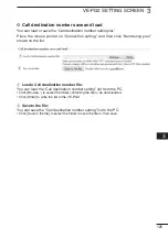
R��l������ ������� ���������g

Set the Call cancel timer, No voice release timer, and Forced disconnect timer.
Place the mouse pointer on �Connection setting,�� then on �VoIP call detail,�� and then 
click �EXT Input (EXT IN)�� shown on the list.

C�ll ������l �������:

Set the call cancel time for when a called VE-PG2 does not reply. After the timer 
ends, the VE-PG2 will cancel the calling.
(Default: 15)
(Select range: 0 (OFF), 5 to 60 seconds)

N� v����� ���l������ �������: 

Set a time, after which if there is no signal, the connection is disconnected.
(Default: 15)
(Select range: 0 (OFF), 5 to 600 seconds)

F������ ������������ �������:

Set a time, after which the communication is automatically disconnected.
(Default: 0)
(Select range: 0 (OFF), 1 to 120 minutes)

 Connection setting (Selective call mode)

q

e

w

Summary of Contents for VE-PG2

Page 1: ...SELECTIVE CALL MODE APPLICATION VE PG2 SETTING SCREEN MAINTENANCE REFERENCE 2 3 4 5 6 7 BRIDGE MODE APPLICATION 1 INSTRUCTION MANUAL RoIP GATEWAY VE PG2...

Page 2: ...er 3 TRX3 74 3 8 TRX EXT EXT Input EXT IN 78 3 9 TRX EXT EXT Output EXT OUT 83 3 10 VoIP call detail Common setting 85 3 11 Emergency notice 87 3 12 Abnormal condition monitor 88 Connection setting Se...

Page 3: ...ion 137 3 34 SYSLOG 139 3 35 Call Reception record 140 3 36 Information list for IP connection 141 4 MAINTENANCE 143 How to restrict of access 144 How to set the VE PG2 internal clock time 145 How to...

Page 4: ......

Page 5: ...SECTION 1 BRIDGE MODE APPLICATION This section describes the VE PG2 setting example in the bridge mode 1 BRIDGE MODE APPLICATION 5 Unicast mode operation 6...

Page 6: ...X1 TRX2 or TRX3 only Using another cable like an Ethernet cable may damage the VE PG2 transceivers or repeaters CAUTION To connect the transceivers or repeaters use only the following cables OPC 2073...

Page 7: ...a A Setting the IP address for Area A Place the mouse pointer on Network setting and then click LAN IP shown in the list Set the VE PG2 s IP address in Area A Click Save and Reboot after setting 2 3 4...

Page 8: ...tion mode Place the mouse pointer on Connection setting and then click Operating mode shown on the list Set the IP communication mode for the transceiver A2 Unicast mode operation Continued Click Save...

Page 9: ...twork connection Place the mouse pointer on Connection setting and then on IP network connection and then click Transceiver 1 TRX1 shown on the list Set the IP address for the transceiver A2 Click Sav...

Page 10: ...Connection setting and then on IP network connection and then click Transceiver 1 TRX1 shown on the list The connection status of the transceiver A2 to the IP network can be displayed on the screen C...

Page 11: ...8 9 10 11 1 Step 5 Area B Setting IP address setting for Area B Place the mouse pointer on Network setting and then click LAN IP shown in the list Set the VE PG2 s IP address in Area B Click Save and...

Page 12: ...ation mode Place the mouse pointer on Connection setting and then click Operating mode shown on the list Set the IP communication mode for the transceiver B2 Unicast mode operation Continued Click Sav...

Page 13: ...Area B Setting the IP network connection Place the mouse pointer on Connection setting and then on IP network connection and then click Transceiver 1 TRX1 shown on the list Set the IP address for the...

Page 14: ...nnection setting and then on IP network connection and then click Transceiver 1 TRX1 shown on the list The connection status of the transceiver B2 to the IP network can be displayed on the screen Conf...

Page 15: ...municate anywhere through the IP network without using hub CAUTION To connect the transceivers or repeaters use only the following cables OPC 2073 For the transceivers or OPC 2074 For the repeaters Co...

Page 16: ...16...

Page 17: ...L MODE APPLICATION This section describes the VE PG2 setting example in the selective call mode 2 SELECTIVE CALL MODE APPLICATION 17 Using with in house sound system 18 Using with an emergency device...

Page 18: ...CAUTION To connect the transceivers or repeaters use only the following cables OPC 2073 For the transceivers or OPC 2074 For the repeaters Connect the specified cables to TRX1 TRX2 or TRX3 only Using...

Page 19: ...ON 2 Step 1 Setting the IP address setting Place the mouse pointer on Network setting and then click LAN IP shown in the list Set the VE PG2 s IP address Click Save and Reboot after setting 2 3 4 5 6...

Page 20: ...d system Step 2 Setting the VE PG2 Operating mode Place the mouse pointer on Connection setting and then click Operating mode shown on the list Set the Operating mode for the VE PG2 Click Save and Reb...

Page 21: ...mouse pointer on Connection setting and then on TRX EXT and then click Transceiver 1 TRX1 shown on the list Set the transceiver control for the Transceiver 1 TRX1 Click to select Notice tone 2 option...

Page 22: ...Set the external input voice setting Input gain HW selection may differ depending on the connected external devices Set the Input gain HW to Maximum or Minimum when the output signal from the external...

Page 23: ...then click EXT Output EXT OUT shown on the list Set the external device output gain Output gain HW selection may differ depending on the connected external devices The external amplifier may output a...

Page 24: ...on Connection setting and then on TRX EXT and then click EXT Output EXT OUT shown on the list Set the broadcast start and end tones for the external amplifier Using with in house sound system Click to...

Page 25: ...evel Place the mouse pointer on Connection setting and then click Priority call Control shown on the list Set the priority level of individual calling for the external amplifier Click to select Priori...

Page 26: ...e pointer on Connection setting and then click Numbering plan shown on the list Set the call destination index number address and port Using with in house sound system Enter 4 Click Save after setting...

Page 27: ...in house sound 2 3 4 5 6 7 8 9 10 11 1 Transceiver 2 Other transceivers External amplifier External device OUT Call destination number 4 IN VE PG2 192 168 0 2 Transceiver 1 TRX1 TRX1 CAUTION To connec...

Page 28: ...92 168 0 2 IN OUT Call destination number 4 Transceiver 1 TRX1 Connect to the transceiver 1 s speaker jack NOTE First connect the transceiver to the VE PG2 using the optional OPC 2073 Then turn ON the...

Page 29: ...ON 2 2 3 4 5 6 7 8 9 10 11 1 Step 1 Setting the IP address setting Place the mouse pointer on Network setting and then click LAN IP shown in the list Set the VE PG2 s IP address Click Save and Reboot...

Page 30: ...device Step 2 Setting the VE PG2 Operating mode Place the mouse pointer on Connection setting and then click Operating mode shown on the list Set the Operating mode for the VE PG2 Click Save and Rebo...

Page 31: ...eiver control Place the mouse pointer on Connection setting and then on TRX EXT and then click Transceiver 1 TRX1 shown on the list Set the transceiver control for the Transceiver 1 TRX1 Click to sele...

Page 32: ...then on TRX EXT and then click EXT Input EXT IN shown on the list Set the external input voice setting Input gain HW selection may differ depending on the connected external devices Set the Input gai...

Page 33: ...ep 5 Setting the external input voice terminal Place the mouse pointer on Connection setting and then on TRX EXT and then click EXT Input EXT IN shown on the list Set the external control terminal eve...

Page 34: ...ng and then on TRX EXT and then click EXT Output EXT OUT shown on the list Set the external device output gain Output gain HW selection may differ depending on the connected external devices The exter...

Page 35: ...ing Place the mouse pointer on Connection setting and then on TRX EXT and then click EXT Output EXT OUT shown on the list Set the broadcast start and end tones for the external amplifier Click to sele...

Page 36: ...vice Step 8 Setting the Emergency notice Place the mouse pointer on Connection setting and then click Emergency notice shown on the list Set the output ports for emergency notice Click to enter the ch...

Page 37: ...ing the calling number Place the mouse pointer on Connection setting and then click Numbering plan Set the call destination index number address and port Enter 4 Click Save after setting Click to sele...

Page 38: ...1 e The VE PG2 sends the emergency broadcast continuously until the emergency device s switch turns OFF The kind of emergency broadcast that is sent depends of the type of external emergency device N...

Page 39: ...1 s speaker jack NOTE First connect the transceiver to the VE PG2 using the optional OPC 2073 Then turn ON the power to the transceiver and the VE PG2 TRX1 CAUTION To connect the transceivers or repea...

Page 40: ...TION 2 Using with a headset Step 1 Setting the IP address setting Place the mouse pointer on Network setting and then click LAN IP shown in the list Set the VE PG2 s IP address Click Save and Reboot a...

Page 41: ...de and EXT I O port mode Place the mouse pointer on Connection setting and then click Operating mode shown on the list Set the Operating mode and external I O port mode for the VE PG2 Click Save and R...

Page 42: ...g Place the mouse pointer on Connection setting and then on IP network connection and then click EXT I O EXT shown on the list Set the destination VE PG2 IP address and port Using with a headset Click...

Page 43: ...eiver control Place the mouse pointer on Connection setting and then on TRX EXT and then click Transceiver 1 TRX1 shown on the list Set the transceiver control for the Transceiver 1 TRX1 Click to sele...

Page 44: ...then on TRX EXT and then click EXT Input EXT IN shown on the list Set the power and input gain for the external headset Input gain HW selection may differ depending on the connected external devices...

Page 45: ...ting and then on TRX EXT and then click EXT Output EXT OUT shown on the list Set the external device output gain Output gain HW selection may differ depending on the connected external devices The hea...

Page 46: ...g the notice tone Place the mouse pointer on Connection setting and then on TRX EXT and then click EXT Output EXT OUT shown on the list Set the notice tone for the headset Click to select Notice tone...

Page 47: ...alling number Place the mouse pointer on Connection setting and then click Numbering plan shown on the list Set the call destination index number address and port Enter 4 Click Save after setting Clic...

Page 48: ...sceiver r Hold down transceiver 2 s PTT and then speak into the microphone Release to receive t Hold down transceiver 2 s PTT and then push to transmit DTMF signals to disconnect the communication rou...

Page 49: ...53 3 2 IP network connection Transceiver 1 TRX1 Transceiver 3 TRX3 57 3 3 IP network connection EXT Input EXT IN 61 3 4 IP network connection EXT Output EXT OUT 65 3 5 IP network connection EXT I O E...

Page 50: ...notice 95 3 17 TRX EXT Transceiver 1 TRX1 Transceiver 3 TRX3 96 3 18 TRX EXT EXT Input EXT IN 102 3 19 TRX EXT EXT output EXT OUT 107 3 20 VoIP call detail Transceiver 1 TRX1 Transceiver 3 TRX3 115 3...

Page 51: ...ork setting 131 3 28 LAN IP 131 System setting 133 3 29 Administrator 133 3 30 Clock 134 3 31 SYSLOG 135 3 32 SNMP 136 Information 137 3 33 Network information 137 3 34 SYSLOG 139 3 35 Call Reception...

Page 52: ...ode shown on the list e Setting items and value display Displays the setting and values when you click the screen name example Clicking Operating mode displays the setting screen r Setting buttons Sav...

Page 53: ...operating mode Place the mouse pointer on Connection setting and then click Operating mode shown on the list When no DTMF function is used Bridge mode must be selected Default Bridge mode Connect tran...

Page 54: ...de setting to Separate mode or Combined mode Default Separate mode When you set EXT I O port mode setting to Separate mode you can separately connect 2 devices to the IN and OUT ports Connection Examp...

Page 55: ...lticast mode or Unicast mode Default Multicast mode w EXT Input port EXT IN Set the communication mode of the IN port to Multicast mode or Unicast mode Default Unicast mode This menu is displayed only...

Page 56: ...Combined mode Set the communication mode of the OUT ports to Multicast mode or Unicast mode Default Unicast mode r Emergency notice Set the communication mode of the emergency notice to Multicast mode...

Page 57: ...d of IP network connection status The default settings q r are dependent on IP communication mode setting q Connection IP address Set the destination VE PG2 s IP address Default Multicast mode 239 255...

Page 58: ...s field of IP network connection status The default settings q r are dependent on IP communication mode setting w Connection port number Set the destination VE PG2 s port number Default Multicast mode...

Page 59: ...o send receive signals You can select Always on connection when the VE PG2 is in the Unicast mode The VE PG2 outputs no audio signals while the TRX1 TRX3 ports detect no signal Transmit only Ports TRX...

Page 60: ...ed in the Unicast mode if you have not set Connection IP address q Status Displays ports TRX1 TRX3 connection settings for the IP network The VE PG2 has 3 statuses Not connected During transmit and Du...

Page 61: ...f IP network connection status The default settings q r are dependent on IP communication mode setting q Connection IP address Set the destination VE PG2 s IP address Default Multicast mode 239 255 25...

Page 62: ...hen click EXT Input EXT IN shown on the list You cannot set these settings when During transmit is displayed in the status field of IP network connection status The default settings q r are dependent...

Page 63: ...and 65534 even numbers only DO NOT set the same port number to TRX1 TRX3 IN or OUT r Connection type Set the signal send receive timing to from IN port Default See EXT Input setting See EXT Input sett...

Page 64: ...Unicast mode if you have not set Connection IP address q Status Displays the IN port connection status for the IP network The VE PG2 has 2 statuses Not connected and During transmit w Reload Click Re...

Page 65: ...tus field of IP network connection status The default settings q e are dependent on IP communication mode setting q Connection IP address Set the destination VE PG2 s IP address Default Multicast mode...

Page 66: ...n the status field of IP network connection status The default settings q e are dependent on IP communication mode setting w Connection port number Set the destination VE PG2 s port number Default Mul...

Page 67: ...ot set Connection IP address q Status Displays the OUT port connection status for the IP network The VE PG2 has 2 statuses Not connected and During receive w Reload Click Reload to reload and display...

Page 68: ...ork connection status The default settings q r are dependent on IP communication mode setting q Connection IP address Set the destination VE PG2 s IP address Default Multicast mode 239 255 255 1 Unica...

Page 69: ...signal timing to from the IN and OUT ports Default See EXT Input setting See EXT Input setting The IN and OUT ports are connected to the IP network to send signals The connection timing is dependent...

Page 70: ...ve not set Connection IP address q Status Displays the IN and OUT ports connection status for the IP network The VE PG2 has 3 statuses Not connected During transmit and During receive w Reload Click R...

Page 71: ...the status field of IP network connection status The default settings q r are dependent on IP communication mode setting q Connection IP address Set the destination VE PG2 s IP address Default Multica...

Page 72: ...ayed in the status field of IP network connection status The default settings q r are dependent on IP communication mode setting w Connection port number Set the destination VE PG2 s port number Defau...

Page 73: ...72 the VE PG2 outputs the emergency notice to the selected port p 129 Transmit only When the emergency signal enter from the IN port the connection timing is dependent on the Valid timing setting p 7...

Page 74: ...cause the port s indicator to mistakenly light Therefore we recommend you always use the default setting Enable Default Enable w Priority receive mode Set the Priority receive mode to Enable or Disabl...

Page 75: ...TRX3 ports to transmit when the VE PG2 receives audio from the LAN port q Attack time Set the delay time for the VOX switch to turn ON after AF signals are received from the LAN port Default 50 Selec...

Page 76: ...to transmit when AF signal are received from the LAN port Default 40 Selectable range 0 to 100 VOX for IP communication Set the VOX setting for the VE PG2 to send audio to the LAN port when the transc...

Page 77: ...ports Default 200 Selectable range 5 to 2000 milliseconds 5 milliseconds steps u Voice delay Set the AF signal buffer time to prevent broken audio Default 5 Selectable range 0 to 500 milliseconds 5 m...

Page 78: ...N port Default IP network EXT Output Sends the AF signal to the OUT port NOTE This item is not selectable if you set Combined mode option in EXT I O port on Operating mode IP network Sends the AF sign...

Page 79: ...ection Sends the AF signal to Input connection port when detecting the control signal e Power for the microphone Enable or disable the VE PG2 to supply power to the external device Default Disable r I...

Page 80: ...lt Momentary Momentary Turned ON when a signal is received from the SW port and turned OFF when no signal is input from it One shot The switch is continuously turned ON when a signal is received from...

Page 81: ...up setting is set to Enable Closed When the SW port is closed Open DC power supply When the SW port is open When the Control input pull up setting is set to Disable Closed No output When a voltage is...

Page 82: ...Default 50 Selectable range 5 to 2000 milliseconds 5 milliseconds steps w Release time Set the time delay for the VOX switch to turn OFF after the AF signal is no longer received from the IN port Defa...

Page 83: ...XT and then click EXT Output EXT OUT shown on the list q Output gain HW Set the audio volume level of the external device which is connected to the OUT port Default Minimum You can select from Maximum...

Page 84: ...not send a control signal Always Sends a control signal when the external device is connected Synchronizing with RTP VoIP Sends a control signal when an AF signal is received The VE PG2 stops sending...

Page 85: ...oIP call detail and then click Common setting shown on the list q Payload time Set the time of data transmit interval Default 20 Selectable from 10 20 30 60 90 or 120 milliseconds w Receive buffer siz...

Page 86: ...in the IP header using the Diffserv Differentiated Service format w Media RTP Set the Priority level and Service type of the sent VoIP packets Priority level Set the TOS priority level code Default 7...

Page 87: ...ort Default o Transceiver 2 TRX2 e Transceiver 3 TRX3 If you click the Transceiver 3 TRX3 check box the VE PG2 sends the emergency notice to the TRX3 port Default o Transceiver 3 TRX3 r EXT Output If...

Page 88: ...is sent the VE PG2 cannot receive signals from the external device that is connected to the IN port w PING transmitting error to appointment host The VE PG2 automatically sends PING commands to the sp...

Page 89: ...g Set the VE PG2 operating mode Place the mouse pointer on Connection setting and then click Operating mode shown on the list When using the DTMF function set the VE PG2 operating mode to Selective ca...

Page 90: ...shown on the list Set the IN and OUT ports to Separate mode or Combined mode Default Separate mode When you set EXT I O port mode setting to Separate mode 2 external devices can be separately connecte...

Page 91: ...TRX1 TRX3 ports Place the mouse pointer on Connection setting and then on IP network connection and then click on one of the Transceiver ports TRX1 TRX2 or TRX3 shown on the list q Destination VE PG2...

Page 92: ...onnection setting and then on IP network connection and then click on one of the Transceiver ports TRX1 TRX2 or TRX3 shown on the list Always on connection mode setting Set the TRX1 TRX3 ports to alwa...

Page 93: ...s and port for the IN port Place the mouse pointer on Connection setting and then on IP network connection and then click EXT Input EXT IN shown on the list q Destination VE PG2 address Set the destin...

Page 94: ...mode Set the IN port to always be connected to the IP network Default Disable Disable The IN port connects to the IP network when transmitting or receiving a signal Client side The VE PG2 always conne...

Page 95: ...r the emergency device Place the mouse pointer on Connection setting and then on IP network connection and then click Emergency notice shown on the list q Destination VE PG2 address Set the destinatio...

Page 96: ...Enable w Priority receive mode Set the Priority receive mode to Enable or Disable Default Disable Disable The VE PG2 allows the VOX to switch the transceiver from receive to transmit normally Enable W...

Page 97: ...a DTMF signal Default Not use This item is appears only when you set Use DTMF call to Enable in DTMF call setting on TRX EXT Transceiver 1 TRX1 Transceiver 3 TRX3 i Calling notice tone to Transceiver...

Page 98: ...eiver ports TRX1 TRX2 or TRX3 shown on the list 0 Disconnect notice tone to Transceiver Set the notice tone to the transceiver when the VE PG2 finishes the selective call connection Default Not use 1...

Page 99: ...F call function or not Default Enable w Inter digit timer Set the time until the VE PG2 automatically calls another VE PG2 after receiving the DTMF signal Default 5 Select range 1 to 10 seconds e OFF...

Page 100: ...Attack time Set the delay time before the VOX switch turns ON after an AF signal is received from the LAN port Default 50 Select range 5 to 500 milliseconds 5 milliseconds steps w Release time Set th...

Page 101: ...an AF signal Default 1000 Select range 5 to 2000 milliseconds 5 milliseconds steps y Release time Set the time of AF detect end timing to the external device that is connected to the LAN ports Defaul...

Page 102: ...N or IP network communication EXT I O port EXT the AF signal is sent to them at the same time Emergency Set the AF signal from the IN port to use for emergency communication NOTE Sends the AF signal t...

Page 103: ...e input gain level of the received AF signal from the external device which is connected to the IN port Default Minimum You can select from Maximum Standard or Minimum Normal input level is follow 0dB...

Page 104: ...ch ON when a signal is received from the SW port and turns the switch OFF when no signal is received One shot Turns the switch ON continuously when a signal is input from the SW port and turns the swi...

Page 105: ...l up setting is set to Enable Closed When the SW port is closed Open DC power supply When the SW port is open When the Control input pull up setting is set to Disable Closed No output When a voltage i...

Page 106: ...ice after the connected transceiver receives an AF signal Default 1000 Select range 5 to 2000 milliseconds 5 milliseconds steps w Release time Set the time of the AF detect end timing to the external...

Page 107: ...EXT OUT shown on the list q Output gain HW Set the audio volume level of the external device which is connected to the OUT port Default Minimum You can select from Maximum Standard or Minimum Normal...

Page 108: ...l setting to Priority calling or High priority calling Fade out is not used before an emergency broadcast is sent This item appears only when you select Separate mode in EXT I O port in Operating mode...

Page 109: ...able from Disable 0 5 1 1 5 2 or 3 This item appears only when you select Combined mode in EXT I O port in Operating mode y Restoration delay time Set the delay time from when a DTMF signal is receive...

Page 110: ...et the switch combination of the A B and C ports when an AF signal is sent through the OUT port Default A C connection A C connection Close the A and C ports when an AF signal is sent through the OUT...

Page 111: ...le from 0 1 0 3 0 5 1 1 5 2 or 3 The A and C ports or the B and C ports close when an AF signal is sent from the OUT port t Event OFF time Set the A and C ports or the B and C ports connection time wh...

Page 112: ...t the desired notice tone type or Not use The selected notice tone sounds in the external device before the communication starts If Not use is selected no tone sounds are sent Default Not use Selectab...

Page 113: ...F signal is sent to the VE PG2 Default 50 Select range 5 to 500 milliseconds 5 milliseconds steps w Release time Set the time of the VOX switch turns OFF when no AF signal is sent to the VE PG2 Defaul...

Page 114: ...Output EXT OUT shown on the list q Broadcast start tone Set the tone type before the broadcast starts Default Single tone 1 Selectable from Not use 4 tone notice up Single tone 1 or Single tone 2 w Br...

Page 115: ...hen on VoIP call detail and then click on one of the Transceiver ports TRX1 TRX2 or TRX3 shown on the list q Send a successful connection tone to VE PG2 Select the desired notice tone type or Not use...

Page 116: ...ransceiver ports TRX1 TRX2 or TRX3 shown on the list q Call cancel timer Set the call cancel time for when a called VE PG2 does not reply After the timer ends the VE PG2 will cancel the calling Defaul...

Page 117: ...ves a signal Place the mouse pointer on Connection setting then on VoIP call detail and then click EXT Input EXT IN shown on the list q Send connect a success tone to VE PG2 Set the communication star...

Page 118: ...timer Set the call cancel time for when a called VE PG2 does not reply After the timer ends the VE PG2 will cancel the calling Default 15 Select range 0 OFF 5 to 60 seconds w No voice release timer S...

Page 119: ...ives a signal Place the mouse pointer on Connection setting then on VoIP call detail and then click EXT Output EXT OUT shown on the list q Send connect success tone to VE PG2 Set the communication sta...

Page 120: ...en on VoIP call detail and then click EXT Output EXT OUT shown on the list q No voice release timer Set a time after which if there is no signal the connection is disconnected Default 15 Select range...

Page 121: ...und quality Place the mouse pointer on Connection setting then on VoIP call detail and then click Common setting shown on the list Receive buffer size Set the buffer time to keep the audio from breaki...

Page 122: ...level for sent VoIP packets Priority Set the TOS priority value Default 7 Select range 0 to 7 7 is the highest priority Service type Set the TOS service type field value Default 0 Select range 0 to 15...

Page 123: ...rentiated Services Code Point value Default 48 Select range 0 to 63 Hexadecimal numeral displayed when TOS Set TOS is composed by 8 bits as follows 1 3 bit Priority value Default 111 4 7 bit Service t...

Page 124: ...selectable w Specific number for OFF hook replying Set the DTMF code for receiving OFF hook The VE PG2 replies when it is called by other VE PG2 Default You can input up to a 4 digit DTMF code 0 9 A B...

Page 125: ...Numbering plan shown on the list q Load a Call destination number file You can load the Call destination number setting list from the PC Click Browse to select the folder containing the file to be dow...

Page 126: ...en click Numbering plan shown on the list q Index Set the index number for the call destination Default 1 w Call destination number Set the DTMF code to call the destination VE PG2 Default Blank e Cal...

Page 127: ...e list Call destination number setting list Display the call destination number setting list Displayed only when a saved destination number has been set q Edit Click Edit when you want to edit the spe...

Page 128: ...ntrol shown on the list q Individual calling Set the priority of the incoming individual call Default Normal calling Selectable from Normal calling Priority calling or High priority calling w EXT Inpu...

Page 129: ...ted port TRX1 TRX2 or TRX3 Default o Transceiver 1 TRX1 Default o Transceiver 2 TRX2 Default o Transceiver 3 TRX3 w EXT Output Sends the emergency notice to the OUT port Default o EXT Output This is n...

Page 130: ...ect signal outputs to the A B or C ports While the error detect signal is sent the VE PG2 can not receive a signal from the external device that is connected to the OUT port Default o PING transmittin...

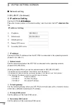
Page 131: ...t this VE PG2 s name Place the mouse pointer on Network setting and then click LAN IP shown on the list Set a name of up to 31 characters a to z A to Z 0 to 9 or are usable The name will be displayed...

Page 132: ...ing example When you set the subnet mask to 255 255 255 248 IP address can be set between 192 168 0 0 and 192 168 0 7 IP address for network devices can be set between 192 168 0 2 and 192 168 0 6 The...

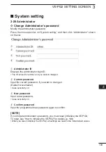
Page 133: ...you cannot change it w Current password Input the current password if you want to change it Default wavemaster Case sensitivity on e New password Input a new password Case sensitivity on r Confirm pas...

Page 134: ...ock Place the mouse pointer on System setting and then click Clock shown on the list q System time Displays the VE PG2 internal clock time w Time setting Displays the time when you access the VE PG2 s...

Page 135: ...o enable or disable to display debug information on the SYSLOG screen Default Disable w INFO Select whether to enable or disable to display information messages on the SYSLOG screen Default Enable e N...

Page 136: ...Enable If you select Enable you can monitor the VE PG2 setting information with the SNMP monitor w Community ID GET Set an ID of up to 31 characters which is required to access the SNMP monitor Defau...

Page 137: ...Interface list You can confirm the VE PG2 s network interface IP address and subnet mask in this screen Place the mouse pointer on Information and then click Network information shown on the list Dis...

Page 138: ...s in this screen Place the mouse pointer on Information and then click Network information shown on the list Displays the VE PG2 s MAC address NOTE The MAC address is unique number which is composed o...

Page 139: ...lay the DEBUG INFO and NOTICE log information When you check each check box the log information is displayed The check box state is not saved Default o 4 DEBUG o 4 INFO o 4 NOTICE When you do not want...

Page 140: ...click Call Reception record shown on the list Displays the VE PG2 communication record entries q Reload Reloads the VE PG2 communication record entries Up to 1000 record entries can be stored If the n...

Page 141: ...nd then click Information list for IP con nection shown on the list Displays the VE PG2 s TRX1 TRX2 TRX3 IN and OUT ports and the emergency notice connecting condition shown on the list The following...

Page 142: ...142...

Page 143: ...or initialize the settings and to set the internal clock time etc 143 4 MAINTENANCE 143 How to restrict of access 144 How to set the VE PG2 internal clock time 145 How to save the VE PG2 setting to th...

Page 144: ...or w Input the Current password New password and Confirm password Input them less than 31 characters Selectable from 0 9 a z and A Z e Click Save r When the login dialog box is displayed enter the log...

Page 145: ...se pointer on System setting and then click Clock w The time when you accessed the VE PG2 s setting screen is displayed in Time setting Click Adjust to set the displayed time to the internal clock NOT...

Page 146: ...nance and then click Save setting w Click Save to the file on Save and load A dialog box appears e Click Save on the dialog box r Select the desired folder then click Save on the window The setting fi...

Page 147: ...ter on Maintenance and then click Save setting w Click Browse on Save and load A Choose file window appears e Select a desired setting file to load and click Open on the window NOTE DO NOT select the...

Page 148: ...ER indicator lights green the VE PG2 initialization is completed OFF Connect the AC adapter LED indicator Lights Blinks Confirm that the POWER indicator lights green and then insert a thin rod into th...

Page 149: ...lick BACK after the initializing is complete NOTE About the initializing condition When All default setting is selected You can restore all the VE PG2 s settings The VE PG2 s IP address is set to 192...

Page 150: ...ecommend that the VE PG2 current setting is saved to the PC before updating the firmware w Place the mouse pointer on Maintenance and then click Firmware update e Click Browse and then select the firm...

Page 151: ...icators light green NEVER disconnect the AC adapter plug from the VE PG2 while updating the firmware If you disconnect it the VE PG2 will be damaged Depending on the update firmware the VE PG2 s IP ad...

Page 152: ...ware extension is dat from Icom web site We recommend that you save the current setting in the PC before updating the firmware w Place the mouse pointer on Maintenance and then click Firmware update e...

Page 153: ...re information the VE PG2 automatically update the firmware If Connection failure or Communication error is displayed on the Firmware information check the following Connect the Ethernet cable to the...

Page 154: ...154...

Page 155: ...SECTION 5 REFERENCE This section describes the troubleshooting and connection with the VE PG2 using telnet 155 5 REFERENCE 155 Troubleshooting 156 Connect with the VE PG2 using Telnet 158...

Page 156: ...use2 The HUB or PC is turned OFF Solution Turn ON the HUB or PC Problem You cannot access the VE PG2 setting screen Possible cause1 The PC s IP address is incorrect Solution Set the fixed VE PG2 s IP...

Page 157: ...onnection does not use the internal CODEC Solution Set the VE PG2 s Input gain HW and Output gain HW NOTE If you set the VE PG2 s external input to Emergency the connections of the transceivers and VE...

Page 158: ...Turn Windows features on or off in Programs and Features r Click the Telnet Client check box t Go to step e in For Windows XP user About telnet command The VE PG2 displays the telnet command list to...

Page 159: ...159...

Page 160: ...1 1 32 Kamiminami hirano ku Osaka 547 0003 Japan A 6838 4US 2010 Icom Inc...

Reviews: