


55
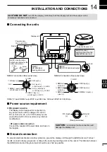
INSTALLATION AND CONNECTIONS
14
D
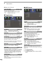
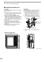
Display unit dimensions
301 (11.9)
119.2 (4.7)
30 (1.2)
74 (2.9)
294 (11.6)
323.5 (12.7)
147 (5.8)
147 (5.8)
■
Installing the display unit
D
Location
Select a place for installation that meets the following
important conditions:
z
The display unit should be placed near the wheel in
the cabin so that an operator may easily view the
radar screen while facing the bow.
z
To minimize interference,
KEEP
the unit
AT
LEAST
THE COMPASS SAFE DISTANCE, stated
in the serial number label on the rear panel, away
from the compass and your navigation receiver.
z
Select a safe location from salt or fresh water spray
or immersion.
z
Select a location where it is easy to perform
maintenance or adjustment after installation.
z
Select a location that can support the weight of the
display unit.
z
DO NOT
select areas subject to extreme heat,
cold, vibrations or direct sunlight.
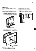
D
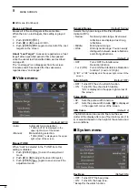
Mounting
The mounting bracket supplied with the display unit
enables “dashboard” or “overhead” mounting.
1.
Hold the mounting bracket up to the selected
location and mark pilot holes for the five
installation holes using the template
on page 62.
2. Drill five holes, 7 mm (0.28 in) in diameter.
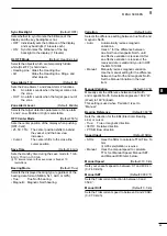
3. Install the bracket using the knob bolts, bolts,
nuts or washers with the supplied accessories.
Flat washer
Spring washer
Bolt
Spring washer
Flat washer
Knob bolt
Nut
4. Adjust the display unit to an appropriate view
angle.
Unit: mm (inch)