background image

 iCanView240/250 User’s Guide 


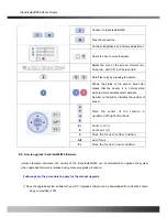
A-2. Mounting Accessories (Optional) 


Rev.1.0 (Dec.2006) 

64 


Summary of Contents for iCanView 240

Page 1: ...iCanView240 250 User s Guide Rev1 0 Dec 2006...

Page 2: ...ill not occur in a particular installation If this equipment does cause harmful interference to radio or television reception which can be determined by turning the equipment off and on the user is en...

Page 3: ...e This symbol is intended to alert the user to the presence of un insulated dangerous voltage within the product s enclosure that can cause electric shock Never install the product in areas exposed to...

Page 4: ...iCanView240 250 User s Guide Revision History Date Rev No Description 2006 12 06 1 0 Creation of the document Rev 1 0 Dec 2006 4...

Page 5: ...odem 22 4 IP Installer 24 4 1 Main window of IP Installer 24 5 Configuring iCanView240 250 in Administrative Mode 25 5 1 Log On 25 5 2 Basic Setup 27 5 3 Network Configuration 29 5 4 Wireless Configur...

Page 6: ...iCanView240 250 User s Guide Appendix 1 On Site Installation of iCanView250 58 Appendix 2 On Site Installation of iCanView240 63 Rev 1 0 Dec 2006 6...

Page 7: ...ernet interface 1 2 Features of iCanView240 250 y World Most Silent Speed Dome IP Camera y 1 channel synchronized real time Video Audio streaming MPEG 4 video ADPCM audio y Bi directional audio commun...

Page 8: ...CAM 704x576 352x288 176x144 y Remote administration control Entire operational parameter set up Software upgrade y Various Mounting Brackets Wall Pipe Gooseneck mounting brackets Corner mount adaptor...

Page 9: ...nation The efficiency of the monitoring can be improved by using this feature used together with DSS Digital Slow Shutter This feature is available only for 18X and 26X zoom module Hot Keys This camer...

Page 10: ...facturing facilities parking lots banks government facilities military etc y Real time Internet broadcasting y Remote monitoring hospitals kindergartens traffic public areas etc y Teleconference Bi di...

Page 11: ...speed dome network camera 2 Manual for outdoor housing 3 Outdoor Housing 4 Wall Mount Bracket 5 Screw M4x15 screw 4EA 6 Safety Cable iCanView240 iCanView250 Outdoor Housing Wall Mount Housing 1 Camer...

Page 12: ...in a PC running i NVR program which is a viewing recording program for a PC Minimum requirement of the PC is described below Recommended Pentium IV 1 8G above CPU 512MB above Main Memory Operating sy...

Page 13: ...external alarm sensors such as the infrared heat magnetic sensor to network camera Sensor type Normal Open or Normal Close can be selected using Virtual System Controller Keyboard Emulator in i NVR fo...

Page 14: ...e of iNVR or NVR Pro LINE OUT Connect external Microphone or audio to network camera Input audio voice is compressed in network camera for synchronized transmission with video to client PC through IP...

Page 15: ...User s Guide A 2 iCanView240 iCanView250 Outdoor Housing Fig 2 3 Dimension of iCanView240 B Exterior and Interior of View B 1 Common part of iCanView240 250 Fig 2 5 Common part of iCanView240 250 Rev...

Page 16: ...les as described in the following table Lens Misc Camera module 22X Zoom Zoom Camera With DSS PAL or NTSC 18X Zoom Sony Zoom Camera PAL or NTSC 26X Zoom Sony Zoom Camera PAL or NTSC 2 5 2 Detailed spe...

Page 17: ...tions Activate preset Group scanning or output on alarm input Aux Output 2 Replay Outputs Auto Flip ON OFF OSD Menu Multiple Languages support Communication RS 485 Functions Protocol Pelco D Power Con...

Page 18: ...ptional Normal mode 0 7Lux 50IRE 0 7Lux 50IRE Min illumination Night mode 0 01Lux ICR On 0 01Lux ICR On 1Lux 30IRE Luminance S N Ratio More than 50dB More than 48dB Video Output VBS 1 0Vp p sync negat...

Page 19: ...ew240 250 is delivered You are asked to configure the system for your environment in administration mode Detailed information of using administration mode can be found in 5 Configuring iCanView240 250...

Page 20: ...ew240 250 Function Signal description Number Connectors Audio Voice in Connect microphone or output from audio devices 1 Mic LINE In Line Out Audio out for speaker Audio from remote site is available...

Page 21: ...250 2 Check if you can receive video data when connecting to iCanView240 250 using the viewer program 4 When one or more IP video products are connected through a IP sharing device i e router to a lar...

Page 22: ...d i NVR S W on PC 3 Using IP Installer S W set up some parameters for communication through IP network Please refer to the IP installer and i NVR user s guide 4 Connect iCanView240 250 with ADSL Cable...

Page 23: ...ement server provides a convenient way of connecting to your network camera under dynamic IP environment Please refer to the Application note regarding Management Server in the CD When connecting iCan...

Page 24: ...iled information of Installing and running IP installer can be found in IP installer user s guide 4 1 Main window of IP Installer Fig 4 1 IP Installer All the basic network parameters needed for the i...

Page 25: ...address window of the Internet Explorer as followings http iCanView240 250 IP address admin htm Example http 172 16 64 133 admin htm If you changed the HTTP port from default value you can login by t...

Page 26: ...g On Screen Factory default User Name and Password are set as root and dw2001 respectively Click on OK button to enter into the Basic Setup page of Administrative Mode If you have changed the username...

Page 27: ...Field Button Select a language of your choice Language Logical name of the iCanView240 250 It is same as the one set up by IP installer You can reassign the system name System Name Audio Input Select...

Page 28: ...s not transmitted if you select NA Check After you finish set up of video and audio for all the channels click on this box to obtain the possible maximum number of users Possible Max Users and remaini...

Page 29: ...Setup the network parameters appropriately in accordance with your network environment Many of the parameters in this page are same as those set up by IP Installer Fig 5 4 Network Configuration Field...

Page 30: ...efer to IP installer user s guide for Clone MAC Each port should have a number below 65 535 RTSP The RTSP port is used for transmitting real time audio video data from the network camera Default is 55...

Page 31: ...to send data in case of alarm Default FTP port number is 21 You can register the network camera to the Management Server DDNS Server for name service to your network camera Log on to server Check this...

Page 32: ...tton Description WLAN Mode Select ESS to use wireless interface If Disable is selected Ethernet interface is used instead of wireless LAN interface WLAN Radio Select the mode of Wireless Radio SSID En...

Page 33: ...es the ID of the connected access point In general the MAC address of the access point is shown Current Channel Indicates the channel number of present connection Signal Strength Indicates the strengt...

Page 34: ...ributes for each user Fig 5 7 User Administrator Time Setup Field Button Sub Field Button Description Administrator Username Admin ID Default ID is root Administrator password Admin password The defau...

Page 35: ...button YES SAVE If you want to restrict viewing access to the iCanView240 250 check at the box left to Yes and click on Save Users need to input ID and password to connect to iCanView240 250 in viewi...

Page 36: ...e time of the PC Set Manually Set the time manually Fill in the fields with desired formats Save the set up parameters SAVE If you lost Administrator s ID and password the only means of recovery is to...

Page 37: ...tual system controller Refer to iNVR user s guide Sensor Setup Name Not applicable for iCanView240 250 It sets the condition of video transmission via FTP or E mail The iCanView240 250 supports 2 type...

Page 38: ...video data for E mail consists of intra frames only in consideration of the limited storage space for E mail account FTP data contains entire video frames Captured Video Transmission By FTP Check to s...

Page 39: ...n Off ON On the alarm output close the relay contact Alarm Device Test OFF Off the alarm output Open the relay contact Sound Test Setup the condition of activating alarm device Select sensor or motion...

Page 40: ...iCanView240 250 User s Guide Save the setup parameters SAVE Rev 1 0 Dec 2006 40...

Page 41: ...Up to 3 regions can be defined Fig 5 11 Motion Region Setup Sub Field Button Description Field Button Not applicable Channel Selection Set the sensitivity in motion detection for each channel 1 is the...

Page 42: ...corresponding colors Legend of the color red region 1 green region 2 blue region3 START Enable selection of rectangular zone start END Enable selection of rectangular zone end SELECT Click on this bu...

Page 43: ...Model Selection Delete Button Press this button to delete the setup of PTZ Your PTZ device needs an ID input ID in this field Click on SAVE to save the ID PTZ Device ID You can check the various oper...

Page 44: ...anning Limitation TEST Test the panning limitation which was set previously Preset Position Set the preset position and test Preset Position Preset Move Select a preset position to move to Movement to...

Page 45: ...check at the box at the left of the Enable data encryption then check at the proper check boxes at the left of Video and Audio After the selection click on SAVE button beneath the Video and Audio che...

Page 46: ...lue to your PC The key values can be downloaded and stored as a file to your PC for reference when you make connection When encryption is enabled the PC client program will ask for particular key valu...

Page 47: ...ield Button Description Field Button Automatic Upgrade This function will be supported in future Automatic upgrade is a feature that enables network camera to upgrade to newly released system software...

Page 48: ...network camera to factory default state By checking on a Radio button Except Network Configuration you can preserve the parameters for the network Checking on All will return all the parameters to fa...

Page 49: ...uide 5 12 Status Report It shows you system records since the system started Fig 5 15 Status Report You can check the problems as well as the versions and event status of the whole system and each mod...

Page 50: ...or for Sensor Input to iCanView240 250 Connect the two wires of the sensors The sensor type can be set in i NVR 1 Please run i NVR connect iCanView240 or 250 and click on the Virtual System Controller...

Page 51: ...ctor for Relay Output from iCanView240 250 A Relay output is provided for connecting alarm devices or for remote on off devices such as light control Relay circuits are normal open and circuits are cl...

Page 52: ...ensor Alarm Device 3 1 Connection of Sensor Fig 6 4 Sensor Device Sensor Power Supply NO NCType Sensor1 Sensor1 12V GND Sensor Device Sensor Power Supply Open CollectorType Photo Coupler Fig 6 4 Conne...

Page 53: ...nView240 250 is successfully installed iCanView240 250 in viewing mode neither channel name nor video is display and eventually timeout message is shown up Check the power and network connection of iC...

Page 54: ...used by performance limitation of the PC Do not run too many programs while running viewer program The other reason could be missing data while transmission from iCanView240 250 Mosaic phenomenon Mosa...

Page 55: ...s or host address in the address input field of the internet explorer Fig 6 6 Web Viewer z Control Panel of Web Viewer Enable bidirectional audio When bidirectional audio is enabled voice from your PC...

Page 56: ...ates the number of sensor Move the center of the camera in up down left right directions Z Z Zoom in Z Zoom out Z F Move the focus to further position A F Auto focus F Move the focus to nearer positio...

Page 57: ...INSTALL button An alert message box will pop up Click OK button then it will start uploading the file This may take some time 6 Upgrade completion message will appear after the system upgrade has bee...

Page 58: ...rations for the installation A 1 Open the Cover of the Dome Camera A 2 Set the DIP switches as in the following picture When using system controller for the control of the dome always set the RS 485 c...

Page 59: ...iCanView240 250 User s Guide A 3 Place the Dome Cover B Installation using Ceiling Mount Notice Ceiling board should be strong enough to hold the weight of approx 2kg Rev 1 0 Dec 2006 59...

Page 60: ...iCanView240 250 User s Guide Rev 1 0 Dec 2006 60...

Page 61: ...iCanView240 250 User s Guide C Installation using Embedded Mount Type Rev 1 0 Dec 2006 61...

Page 62: ...iCanView240 250 User s Guide Rev 1 0 Dec 2006 62...

Page 63: ...iCanView240 250 User s Guide Appendix 2 On Site Installation of iCanView240 A Basic Components and Mounting Accessories A 1 Basic Components Rev 1 0 Dec 2006 63...

Page 64: ...iCanView240 250 User s Guide A 2 Mounting Accessories Optional Rev 1 0 Dec 2006 64...

Page 65: ...ng using Wall Mount Bracket The wall should be strong enough to hold 4 times of the weight of the camera 5 3 KG This means that the wall should withstand weight of 21 2 KGs in the minimum B 1 Install...

Page 66: ...iCanView240 250 User s Guide C Pipe Mounting C 1 Preparations for the Mounting C 2 Cabling for the Pipe Mounting Rev 1 0 Dec 2006 66...

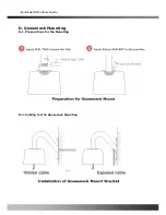
Page 67: ...iCanView240 250 User s Guide D Gooseneck Mounting D 1 Preparations for the Mounting D 2 Cabling for the Gooseneck Mounting Rev 1 0 Dec 2006 67...

Page 68: ...all a corner mount adaptor on the corner of wall E 2 Use wall or gooseneck mount bracket to finish installation F Pole Mounting F 1 Install a pole mount adaptor on the pole F 2 Use wall or gooseneck m...

Page 69: ...ure On over 45 Off below 35 Fan control temperature 40 60 Operating temperature Below 90 Operating humidity IP 66 Waterproof Capacity Poly Carbonate Bubble Aluminum Body Construction 253 diameter x 30...

Page 70: ...iCanView240 250 User s Guide H 2 Dimension of Outdoor Housing 97 0 253 0 190 0 210 0 UNITS m m 580 0 Rev 1 0 Dec 2006 70...

Reviews: