background image


Operation 

3-17 

ImageTracDS 1210/1155 User’s Manual 


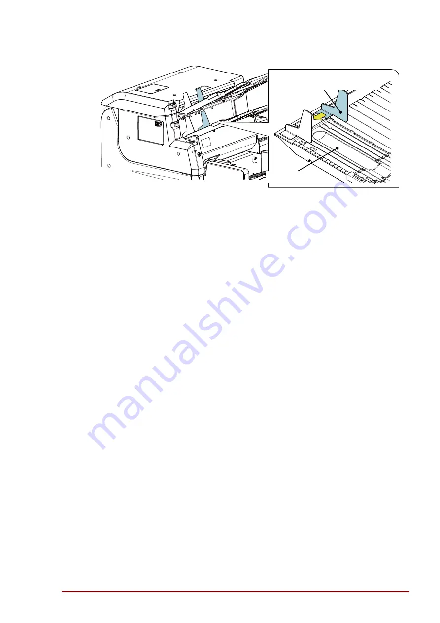
4.  Adjust the Output Tray Guides to slip width. 


5.  Start scanning from the application program. 

Do not add papers during scanning. 

6.  Remove the scanned papers from the Output Tray. 


3.4.3  Automatic Scanning and Input Tray Position 

This section explains Automatic Scanning and Input Tray Position settings those are suited to 
scanning small amount of documents repeatedly. 


  Automatic Scanning 

When "Automatic Scanning” is selected, a scan is started automatically when a sheet is set in 
the Input Tray. 

1.  Start scanning on the application program. 

2.  Set documents into the Input Tray then a scan is started automatically. 

If you have more documents to scan, set those into the Input Tray repeatedly. 

3.  Automatic Scanning is terminated from the application program. 

Or you can terminate Automatic Scanning by a long press of the Operation Button. 

4.  Remove the scanned papers from the Output Tray. 


  Input Tray Position settings 

“Input Tray Position” parameter on feeding settings of the host application specifies the Input 
Tray position. 

 Normal: 

Descends to a bottom 

 Level 1:    5 mm descent 

 Level 2:    15 mm descent 

Output Tray 

Output Tray Guide 

Summary of Contents for ImageTracDS 1210

Page 1: ...ImageTracDS 1210 1155 User s Manual Version 1 1...

Page 2: ...tary information and trade secrets of Imaging Business Machines LLC embodying substantial creative efforts and confidential information ideas and expressions no part of which may be reproduced or tran...

Page 3: ...tion and Operation Button 12 1 7 System for Scanning Operation 14 1 7 1 System Configuration 14 1 7 2 Requirement for PC Environment 15 1 8 Software 16 1 8 1 Software to be provided 16 1 9 Contents of...

Page 4: ...very from Paper Jam in Top Unit 36 3 7 2 Recovery from Paper Jam in Main Unit 37 3 7 3 Handling Paper Jam when using the Extension Plates 39 4 1 4 1 Maintenance Conducted by Users 2 4 2 Cleaning 5 4 2...

Page 5: ...155 User s Manual 4 6 1 Image Sensor Test 29 4 6 2 Imprint Test 30 4 6 3 Sheet Counter Settings 33 4 6 4 Imprint Settings 38 4 6 5 Power Save Mode Settings 43 4 6 6 USB Operation Mode 44 4 6 7 Image S...

Page 6: ...al distributor Translations English translation provided the original non English published language supersedes any translated version of the document This English version is a preliminary documentati...

Page 7: ...a abnormality The user must be reliable for scanned data validation ibml does not take on any responsibility for any damage caused by using a poor quality sheet or sheet not up to standard Never use t...

Page 8: ...are written on the labels below Symbol Description This symbol is accompanied by text to indicate that the following information is related to safety DANGER Indicates an imminent hazardous situation...

Page 9: ...t plug too many leads into a single outlet If you do so a fire may occur Also too many leads may activate the circuit breaker and affect other devices and operations Power supply Do not use the device...

Page 10: ...ur Air Vent The air vent is provided to prevent the internal temperature from rising too high Do not block the air vent with an obstacle over or in front of it If you do so the internal temperature ri...

Page 11: ...hen setting original manuscripts or removing jammed papers pay attention not to cut your finger with the edge of the paper Do not bring your face close to the device when it is operating Paper ejected...

Page 12: ...e Top Unit with your hand while you work 3 32 Push until Top Unit latches completely by pushing PUSH Label If you use the device when unlatched it may cause paper jams etc 3 33 When the Main Unit is o...

Page 13: ...e Stopper longer than the paper length Or paper jam may happen 3 7 3 9 When sliding the Sheet Gude hold the center of it or it may be damaged 3 11 3 12 Some condition of the documents occurs paper jam...

Page 14: ...to exposure to direct sunlight 4 21 When you clean use nonwoven fabric or other material that does not create dust The quality of printout may be deteriorated by fabric on nozzle 4 25 If you use roll...

Page 15: ...g the device Be sure to hold the bottom of the device If you hold input output tray or other parts the device may break or drop When placing the device on the floor be careful not to catch your finger...

Page 16: ...include these data they need to be checked Misread ibml does not take on any responsibility for any damage caused by inability or error in scanned or data abnormality The user must be responsible for...

Page 17: ...label regularly so the text be read clearly If the label is broken contact the service personnel and ask for a new label Disposal of Scanner and Consumables Scanner and Consumables should be disposed...

Page 18: ...about Overview of Image Scanner 1 1 Device 1 2 Unique Features 1 3 Specifications 1 4 Major Component 1 5 Consumables and Periodic Replacement Maintenance Parts 1 6 LED Indication and Operation Butto...

Page 19: ...on An application program controls scanning operation the scanner scans each sheet and transfers data to the host Control Unit Application Program USB Controller USB Driver Windows 7 8 8 1 Imprinter B...

Page 20: ...drop colors arbitrary with color curve Imprint front back option Max 38 characters one location Max 17 characters two locations Delete old data and print new information Prohibit redundant scanning Si...

Page 21: ...f super long sheet Multi Feed Detection Sensor Five Ultrasonic Sensors Imprinter Side Front Back option Number of characters Max 38 characters 1 location Max 17 characters each 2 locations Character n...

Page 22: ...om Power Save Mode 3 Hand Feeding Manual Feed Switch Used for scanning a single sheet and or transparent holder manually Input Tray Tray to put document in for scan Sheet Guide Used for aligning the r...

Page 23: ...Do not change the settings or operation mode may be changed to the maintenance mode Name Use USB Cable Connect the device to host USB Connector Connect the device to host via USB cable Power Connecto...

Page 24: ...ink cartridge is unpacked Ink cartridge has an expiration date for installation The expiration date is printed on the package If you use ink cartridge after the expiration date print quality may be d...

Page 25: ...1 8 Overview ImageTracDS 1210 1155 User s Manual No Part Name Picture 1 Pick Roller 2 Separation Roller 3 Reverse Roller 4 Roller Set Pick Roller 2 Separation Roller 2 Reverse Roller 2...

Page 26: ...Picture 6 Pick Unit assembly Excluding rollers Although the pictures include rollers the provided item does not include rollers top rear 7 Reverse Roller assembly Excluding rollers Although the pictu...

Page 27: ...eTracDS 1210 1155 User s Manual No Part Name Picture 8 Ribbon cassette for front imprinting E 4181 Black Z 4181 Red E 4181T Black Tank Z 4181T Red Tank 9 Ink Cartridge for back imprinting option Black...

Page 28: ...work even after warning because of differences of various factors but replacement is recommended On the contrary there are also cases that the rollers need to be replaced before replacement warning h...

Page 29: ...en slow blink green red 0 0 5 1 1 5 2 2 5 s Power save mode Start scanning or press the Operation Button to resume job Red blink green red 0 0 5 1 1 5 2 2 5 s Paper jam error Remove jammed sheets and...

Page 30: ...n It can stop scanning or restore the device from the power save mode The operations are as follows Operation Button Action Press it shortly Restore from the Power Save Mode Press it longer than 1 sec...

Page 31: ...al 1 7 System for Scanning Operation 1 7 1 System Configuration Application program should use the TWAIN driver Character recognition and image processing should be done by application programs Applic...

Page 32: ...Right click on the start screen and click in order of All apps Control Panel System and Security and System System requirement for the host ITEM Recommended Specifications Remark Processor CPU Intel C...

Page 33: ...re to be provided No Product name Remarks 1 DS 1210 1155 Scanner Driver Installed on DS 1210 or DS 1155 when using SoftTrac Capture Suite Installed on DS 1210 when using third party application 2 DS 1...

Page 34: ...nce the ink cartridge bundled with the DS 1210 equipped the back imprinter option is used for only printer check purpose at the device installation the specifications of ink cartridge described in doc...

Page 35: ...1 18 Overview ImageTracDS 1210 1155 User s Manual...

Page 36: ...Installation 2 1 ImageTracDS 1210 1155 User s Manual 2 Installation This chapter explains about scanner installation 2 1 Power Supply 2 2 Space for Device Installation...

Page 37: ...264V 50 60 1 Hz 1 2 PS cable Use the attached PS cable Specification for inlet IEC60320 C13 3 PS outlet PS outlet should be in Accordance with the National standard 2 4 Grounding Dedicated grounding...

Page 38: ...area Maintenance job area requires 1 000 mm from around the scanner Please keep maintenance area in maintenance Do not put things within about 300 mm from air vent As the exhaust temperature is higher...

Page 39: ...Installation 2 4 ImageTracDS 1210 1155 User s Manual...

Page 40: ...r s Manual 3 Operation This chapter explains scanning and operation of scanner 3 1 Power ON OFF 3 2 Preparing to scan 3 3 Scanning Operation 3 4 Scanning features 3 5 Imprinting Operation 3 6 Multiple...

Page 41: ...ognized by the OS or may not start normally In these cases turn the power OFF and wait 5 seconds then turn the power ON NOTICE Before connecting disconnecting the USB cable the Image scanner should be...

Page 42: ...here are no papers left in the Input Tray 3 Check if the LED Indicator lit green Ready 4 Press the part of the Power switch on the front of the device the device goes to Standby mode 5 If you do not u...

Page 43: ...per 3 Sealed post card 3 non carbon paper A paper B paper C paper Thickness 41 209 g m 2 11 56 lbs Dropout color Red Green Bule Multiple colors Costom Scanning of mixed paper 3 1 Scannable paper size...

Page 44: ...Tray Guides spread them to the widest position NOTICE When using the Output Tray Guides adjust them approx 5 mm wider than paper width Or paper jam may happen When using the Output Tray Guides followi...

Page 45: ...length is 8 27 to 18 inches 210 mm A4 landscape to 458 mm use the Stopper 2 and the Extension Trays if necessary When the paper length is less than 8 27 inches 210 mm A4 landscape When setting mixed s...

Page 46: ...jam may happen 3 Pull the Stopper 1 to the near side then it will stand up 4 Place the paper to scan into the Output Tray and slide the Stopper 1 position Adjust it approx 1 2 inch 3 scale increments...

Page 47: ...18 inches 210 mm A4 landscape to 458 mm When setting mixed size paper adjust the Stopper and the Extension Trays to the longest paper 1 If the Stopper 1 stands up slide it to the end of the near side...

Page 48: ...elow NOTICE Adjust the Stopper longer than the paper length Or paper jam may happen 6 Place the paper to scan into the Output Tray and adjust the Extension Trays in the order of the Extension Tray 1 t...

Page 49: ...with ink or adhesive wait until dries Align the edges of papers to avoid skew If the tip of the sheet is bent unbend it If the sheet is wrinkled or curled smooth it out 2 Separate the papers as follow...

Page 50: ...ording to documents 2 Slide the Sheet Guide wider than the stack of papers 3 Place the paper stack face up on the Input Tray and align it to the top edge and left edge 4 Slide the Sheet Guide and pres...

Page 51: ...top 4 Align the papers to the top and left edges 5 Place the paper stack as face up on the Input Tray and align it to the top edge and left edge 6 The Sheet Guide aligned with largest papers Check th...

Page 52: ...hose coefficient of friction is high might not be scan well with OCR papers and regular papers Perforated paper paper with sprocket heat seal wet seal and dry seal cannot be mixed When mixed size pape...

Page 53: ...ion Start scanning from the host system 1 Launch the application program on the host system 2 Select the scanning job in the application program 3 Start scanning from the host application Do not add p...

Page 54: ...orce parameter on feeding settings of the host application Separating Force parameter specifies the force level of paper seperating in the feed mechanism in 5 steps When setting Thin Sheet Scannig mod...

Page 55: ...lips use Sheet Guide_S that is included width shipment Operation 1 Mount the Sheet Guide_S on the Sheet Guide by attaching the 2 pawls on the Sheet Guide_S 2 Place the small slips on the Input Tray an...

Page 56: ...arted automatically when a sheet is set in the Input Tray 1 Start scanning on the application program 2 Set documents into the Input Tray then a scan is started automatically If you have more document...

Page 57: ...there may be multiple sheet feed problems Example paper for the manual scanning Conduct the manual scanning with the Manual Feed Switch for these type of paper to avoid paper jam problem multiple she...

Page 58: ...be prevented from being dirt transcription borrowed sheet etc Sheet out of the specification of 48mm X 74mm or less it is necessary to put a pasted board of the sheet specification Sheet with the perf...

Page 59: ...bon paper which consists of multiple sheets is scanned there may be ink transfer because of pressure by rollers To scan non carbon sheet it is important to feed one sheet by one and check image qualit...

Page 60: ...ray U for a small amount of long papers There are two types of Extension Plate depending on paper length Extension Plate attatched paper length 18 to 26 inches 458 to 660mm Up to 30 sheets 75 g m2 20l...

Page 61: ...he Extension Tray 2 and the Stopper 2 from the Input Tray 2 Hold the Extension Plate in the direction of following figure and push down the Extension Tray 2 slightly approx 1 mm Then insert the Extens...

Page 62: ...xtension Tray 2 and the Stopper 2 are fully extended 5 Attach the other Extension Plate to the Output Tray U following the same procedure Detaching the Extension Plates Hold the Extension Tray 1 and p...

Page 63: ...e type of Extension Plates Scanning of long sheet parameter The limit number of long paper sheets 75 g m2 20lbs 2 9 to 18 inches 74 to 458 mm N A OFF N A 18 to 26 inches 458 to 660 mm Extension Plate...

Page 64: ...t length is less than 34 inches 864 mm but need operator assistance to scan Hand Feeding Mode The Hand Feeding mode is used for scanning papers that need operator assistance 1 Select Hand Feeding mode...

Page 65: ...or each sheet group Document width direction Outside 11 2 mm from the left edge of document Inside 21 2 mm from the left edge of document Rear Feeding direction 8 2 mm from the bottom edge of document...

Page 66: ...irection Imprint Location 2 Deletion Location 1 Sequential No A00123 Location 1 A00123 Location 2 VVVVV Feed direction A00012 Example of imprinting Rear One location or Location 1 A00012 Imprint one l...

Page 67: ...ers 2 4 A Note p 2 62 mm character for standard font size 5 24 mm character for larger font size Note L1 or L2 should not be larger than L 10 Rear option W 11 2mm fixed A 8 2mm fixed one location two...

Page 68: ...er There are 2 print locations for the front imprinter CAUTION When the Top Cover is open it may close naturally and catch your hand Be sure to hold the cover with one hand when operating while the co...

Page 69: ...ve the Ribbon Cassette Tray according to the print location 4 OUTSIDE Position is the spot where the Ribbon Cassette Tray stops when you pull it out INSIDE Position is the spot where the Ribbon Casset...

Page 70: ...rs any multiple layers of paper tape and seals will affect the detection accuracy Relaxation of multi feed detection In case there are attachments in the area of multi feed detection it is possible to...

Page 71: ...ings while you work 3 7 1 Recovery from Paper Jam in Top Unit CAUTION When the Top Unit is open hands and objects can be caught by the Top Unit if the Top Unit closes unexpectedly Make sure you hold t...

Page 72: ...hen unlatched it may cause paper jams etc 3 7 2 Recovery from Paper Jam in Main Unit CAUTION When the Main Unit is open hands and objects can be caught by the Main Unit if the Main Unit closes unexpec...

Page 73: ...direction of the arrow When you close the Main Unit press both PUSH labels on the side with fingers and push down the unit until it laches NOTICE Push until Main Unit latches completely by pushing PUS...

Page 74: ...Operation 3 35 ImageTracDS 1210 1155 User s Manual 3 7 3 Handling Paper Jam when using the Extension Plates When uisng the Extension Plates close the device gently to avoid damage...

Page 75: ...Operation 3 36 ImageTracDS 1210 1155 User s Manual...

Page 76: ...for paper transfer separation which would deteriorate due to time and usage and have to be replaced To avoid failures caused by these parts daily and preventive maintenance should be conducted Related...

Page 77: ...papers As paper dust from sheets may affect images perform inspection and cleaning daily No Item Inspection Frequency Remarks 1 Cleaning Image Sensor 4 2 1 Daily and when something abnormal happens R...

Page 78: ...Maintenance 4 3 ImageTracDS 1210 1155 User s Manual The locations of major components Top Unit is opened Platen PC41 PC41 PC42 PC42 PC52 PC52 PC51 PC43...

Page 79: ...geTracDS 1210 1155 User s Manual The locations of major components Main Unit is opened Perforated sheets produce a lot of dust so more frequent cleaning is required PC21L PC21R PC11 PC20 PC31 PC31 PC2...

Page 80: ...TICE If the surface of the image sensor gets dirty with ink adhesives dust from papers or fingerprints device failure or scanning error may occur Clean the image sensor regularly before operation and...

Page 81: ...unexpectedly Make sure you hold the Main Unit with your free hand while you work 1 Operate the Main Latch Button and open the Main Unit 2 As shown in the figure below remove the paper dust and foreig...

Page 82: ...nit if the Main Unit closes unexpectedly Make sure you hold the Main Unit with your free hand while you work Detectors PC11 PC20 PC21L PC21R PC31 1 Operate the Main Latch Button and open the Main Unit...

Page 83: ...cloth etc around fingers and clean the photo sensor Be careful not to pinch your fingers 4 Open the Reverse Cover Twist gauze damp cloth etc around fingers and clean the photo sensor After cleaning c...

Page 84: ...it closes unexpectedly Make sure you hold the Main Unit with your free hand while you work 1 Operate the Top Latch Button and open the Top Unit 2 Clean the detectors plastic tips of photo sensor with...

Page 85: ...nual 3 Prepare appropriate width paper so that the paper can insert between the rollers Then repeatedly insert and remove the paper between the rollers to clean the sensor 4 Close the Top Unit by push...

Page 86: ...Unit with your free hand while you work NOTICE Do not clean the ultrasonic sensors with excessive force If you do position detection may be affected and malfunction may result 1 Operate the Main Latc...

Page 87: ...unt exceeds the Replacement Cycle replace each roller according to the procedure of this section No Product Name Number of Items Replacement Cycle 1 Pick Roller 2 One year or about 1 000 000 sheets of...

Page 88: ...toward to remove 4 Open the Pick Top Cover in the direction of the arrow 5 Remove the Pick Shaft assembly and Separator Shaft assembly Hook Pick Top Cover Pick Bottom Cover Pick Shaft assembly Separat...

Page 89: ...times while pushing it firmly Replacing Separator Rollers 1 Remove the Separator Roller from the Pulley Sparate a Separator Roller is just inserted without glue so you can remove it with your hand an...

Page 90: ...in subsection 4 6 3 Sheet Counter Settings 1 Operate the Main Latch Button and open the Main Unit 2 Hook your fingers on the edge of the Reverse Cover assembly 3 Pull the Reverse Cover assembly in th...

Page 91: ...in reverse Reverse Roller has no mounting direction 7 After you install a Reverse Roller in order for the Pulley Reverse and the Reverse Roller to fit together completely rotate the Reverse Roller wi...

Page 92: ...hile you replace the Ribbon Cassette Or Ribbon Cassette and Imprinter may be damaged 1 Operate the Top Latch Button and open the Top Unit 2 Press the PUSH OPEN mark on the Imprint Cover Front at the l...

Page 93: ...e Tray to the outside position Only in the case of the Ribbon Cassette Tray is at inside position 5 Pull out the Ribbon Cassette 6 Push the Ribbon Cassette Tray to the inside position where the Ribbon...

Page 94: ...the Cassette to the Ribbon Cassette Tray carefully so the Tip does not get stuck Push it until you hear a clicking sound 9 Set the Tray to the original position in instruction 3 10 Close the Imprint C...

Page 95: ...ing in eyes and getting on skin and clothes If ink should enter eyes or be swallowed by mistake wash the eyes or gargle and contact the nearest medical service 4 5 1 Exterior View and Component Names...

Page 96: ...re you start using the scanner make sure you run the Imprint Test in the Scanner Utility to check the printout quality You may have to repeat the Imprint Test before you get good printout quality depe...

Page 97: ...nt Test as described in subsection 4 6 2 Imprint Test Preparation of ink cartridge 1 Open a package and take out ink cartridge The ink cartridge is packed in a pair of cases as shown in the figure bel...

Page 98: ...he Imprint Cover Rear on the Top Unit 1 Move the lever on the Ink Jet Print assembly in the direction of the arrow and release the ink cartridge fixed 2 Grab the knob on the ink cartridge and pull the...

Page 99: ...with installing the ink cartridge 2 Gab the knob on the ink cartridge and insert the ink cartridge from front side A boss protrudes from the ink cartridge so do not force the ink cartridge into the p...

Page 100: ...rub the unit with excessive force If the unit is wet wipe it off with a dry cloth or the like Nozzle Unit Gently put a wet clean cloth on the unit If you see ink on the cloth it is sufficient If ink i...

Page 101: ...sult shows unclean locations in the window 1 2 Imprint Test Executes an Imprint Test to check that ink cartridge is ready for printing Executes the Imprint Test for both front and rear side The steps...

Page 102: ...or Windows 7 Click the Start button From the menu select All Programs ImageTracDS 1210 Scanner Utility for End User and then click the Scanner Utility b For Windows 8 8 1 Select ImageTracDS 1210 Scann...

Page 103: ...s Manual 2 The Menu window of Scanner Utility below is displayed Image Sensor Test 4 6 1 Imprint Test 4 6 2 Sheet Counter Settings 4 6 3 Imprint Settings 4 6 4 Power Save Mode Settings 4 6 5 USB Opera...

Page 104: ...the glass and the Black White Background parts on both Image Sensors Front Back Close the device 3 Click the Contamination Check to check the Result box If the Result box shows follow the displayed me...

Page 105: ...nput Tray 1 In the Menu Window select the Imprint Test and click the Execute The Imprint Test window is displayed The followings are default settings Sheet size A4 Landscape Imprint Not print 2 For th...

Page 106: ...de Then type in print characters In imprint test the scanner cannot print on both side simultaneously If you select the Front side the Characters for Imprint Front are F 0123456789 by default You can...

Page 107: ...32 ImageTracDS 1210 1155 User s Manual 5 In the window below for the Imprint Test click the Yes 6 When the print test finishes the window below is displayed Click the OK 7 Click the End to return to t...

Page 108: ...ow select the Sheet Counter Settings and click the Execute The Information display in the Sheet Counter Settings window is displayed The Roller information shows the sheet count and the latest replace...

Page 109: ...10 1155 User s Manual 3 After you replaced rollers in the Information display window select check box in the Reset sheet count for the rollers you replaced Click the Execute to reset the Sheet counts...

Page 110: ...Maintenance 4 35 ImageTracDS 1210 1155 User s Manual 6 Confirm that the Sheet counts are reset to 0 and that the replacement date has been updated 7 Click the End to return to the Menu Window...

Page 111: ...CE If you use rollers beyond their replacement cycle by changing following settings mis feed paper jam may happen Manage settings corresponding to your scanning operation 1 In the Sheet Counter Settin...

Page 112: ...g checkmark the Roller replacement warning timing setting and select the Do not report 4 Click the Execute to update the setting 5 In the window below click the Yes 6 Click the OK 7 Confirm that the s...

Page 113: ...artridge Settings window is displayed In the window Ink level The number of printed sheets Sheets and Cartridge replacement date about currently using ribbon cassette or ink cartridge are displayed In...

Page 114: ...1210 1155 User s Manual 3 If you replace the rear ink cartridge in the Information display window checkmark the Ink level reset for the rear ink cartridge Then click the Execute 4 In the window below...

Page 115: ...nfirm the following Ink level is 100 The number of printed sheets is 0 Sheets Cartridge replacement date is updated New ink cartridge should be checked to print out characters properly by running the...

Page 116: ...esponding to your scanning operation 1 In the Imprint Settings window select the Parameter Settings tab to set rear cartridge parameters 2 Select the Ink level warning timing setting Ink replacement w...

Page 117: ...ImageTracDS 1210 1155 User s Manual 3 In the window below click the Yes 4 Click the OK 5 Confirm that the settings are changed correctly in the Parameter Settings window 6 Click the End to return to...

Page 118: ...Mode Settings window is displayed In the window Transition time to the power save mode is displayed 2 To change the transition time specify the value between 1 and 240 in minutes and click the Execute...

Page 119: ...You can confirm USB transfer mode 1 In the Menu Window select the USB Operation Mode and click the Execute The USB Operation Mode window is displayed In the Transfer mode Super Speed USB3 0 or Hi Spee...

Page 120: ...dow sensitivity for judgement of contamination level and white level reduction warning timing are displayed 2 To change the sensitivity for judgement of contamination level select the sensitivity sett...

Page 121: ...Maintenance 4 46 ImageTracDS 1210 1155 User s Manual...

Page 122: ......

Page 123: ......

Reviews: