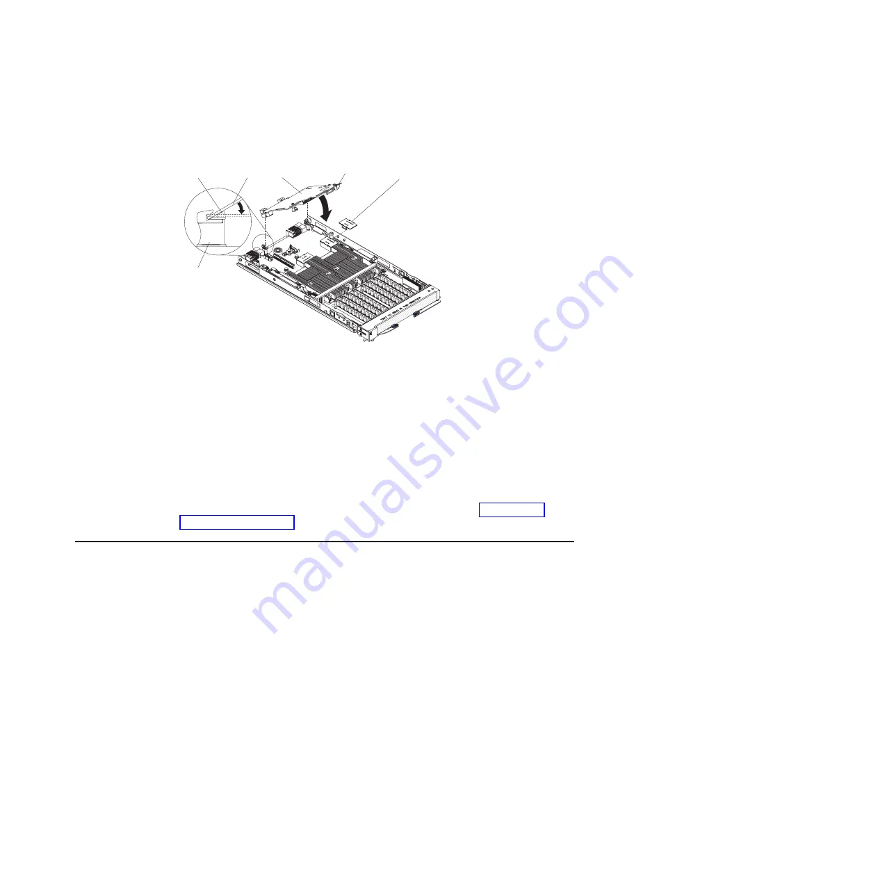
9.
Slide
the
locator
pin
holes
on
the
expansion
card
over
the
locator
pins.
The
card
rests
on
the
locator
pins.
10.
Carefully
press
the
expansion
card
into
position.
Be
sure
that
the
ball
socket
on
the
card
is
over
the
corresponding
ball
stud
on
the
main
board.
Use
the
blue
areas
only
to
avoid
damage
to
the
card.
11.
Check
that
the
blue
locking
clip
is
horizontal
and
that
there
is
no
gap
between
the
card
and
the
connector.
Attention:
The
connectors
on
the
system
board
and
the
high-speed
expansion
card
are
not
designed
for
repeated
removal
or
replacement
of
components.
Avoid
removing
the
card
once
it
is
in
position,
If
you
have
other
options
to
install,
do
so
now.
Otherwise,
go
to
Adding
or
changing
system
memory
There
are
8
DIMM
slots
for
system
memory.
Each
IBM
PowerXCell
8i
processor
has
two
memory
channels
and
there
are
two
DIMM
slots
per
memory
channel.
You
can
use
VLP
DDR2
1
GB,
2
GB,
or
4
GB
memory
modules.
The
maximum
memory
configuration
has
a
4
GB
memory
module
in
each
DIMM
slot
which
provides
16
GB
to
each
processor
and
32
GB
in
total.
Expansion
connector
cover
Expansion card
Expansion
card
standoff
Locator pin
Locking clip
Expansion card
Figure
15.
Positioning
the
high-speed
expansion
card
Chapter
4.
Installing
and
removing
replaceable
units
27
Summary of Contents for QS22 - BladeCenter - 0793
Page 3: ...BladeCenter QS22 Type 0793 Installation and User s Guide...
Page 8: ...vi BladeCenter QS22 Type 0793 Installation and User s Guide...
Page 30: ...14 BladeCenter QS22 Type 0793 Installation and User s Guide...
Page 34: ...18 BladeCenter QS22 Type 0793 Installation and User s Guide...
Page 54: ...38 BladeCenter QS22 Type 0793 Installation and User s Guide...
Page 70: ...54 BladeCenter QS22 Type 0793 Installation and User s Guide...
Page 84: ...68 BladeCenter QS22 Type 0793 Installation and User s Guide...
Page 112: ...96 BladeCenter QS22 Type 0793 Installation and User s Guide...
Page 113: ......
Page 114: ...Part Number 44R5161 1P P N 44R5161...


