i.
Attach the longer LED panel cable that comes with this kit to
J29
.
j.
Align the processor board with the connector on the system board (use the alignment pin on the
system board connector as a guide) and carefully seat the processor board.
Note:
Do not force the processor board into place.
k.
Press the processor board latch lever to lock the board into place; then, press down on the
processor board to ensure proper seating.
l.
Reconnect the processor board cables that you removed in step 15f on page 8.
m.
Skip to step 17 on page 10 to continue the installation.
16.
For Netfinity 5100 servers, you must disconnect the other end of the cable from the system board
connector
C
.
D
C
B
A
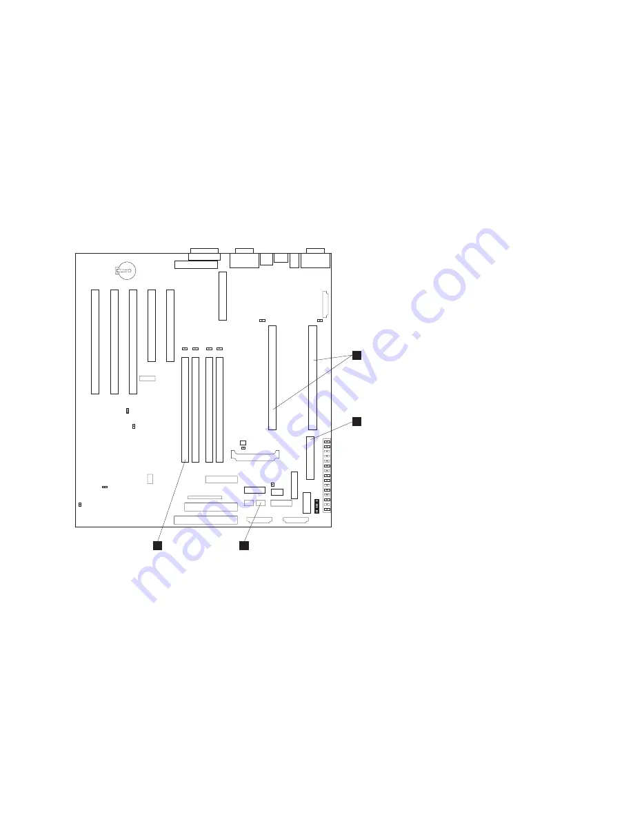
Figure 11. Locating the LED panel cable connector on the system board
Note:
The microprocessor connectors
A
, main power connector
B
, and DIMM sockets
D
are
shown to assist you in locating the LED panel cable connector
C
.
Pull the cable all the way through the opening in the server at the LED panel old position; then,
reconnect the cable to the system board connector
C
, making sure that the connector detent is
facing toward the front of the server, and continue with step 17 on page 10.
Preparing the server for rack installation
9
Summary of Contents for Netfinity 5Ux24D Tower-to-Rack Kit
Page 1: ...IBM IBM Netfinity 5Ux24D Tower to Rack Kit Installation Instructions ...
Page 2: ......
Page 3: ...IBM IBM Netfinity 5Ux24D Tower to Rack Kit Installation Instructions ...
Page 8: ...vi 5Ux24D Tower to Rack Kit Installation Instructions ...
Page 37: ......
Page 38: ...IBM Part Number 19K0825 Printed in U S A 19K 825 ...


