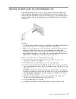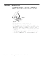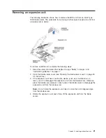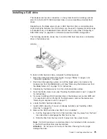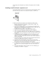
Installing
an
expansion-card
bracket
If
you
are
installing
a
standard-form-factor
expansion
card,
you
must
also
install
an
expansion
card
tray.
The
expansion-card
bracket
comes
in
the
box
with
your
blade
server.
Some
blade
server
models
might
already
have
an
installed
expansion-card
bracket
instead
of
a
SAS
drive
tray
where
the
connector
for
SAS
drive
1
is
located
(see
“Blade
server
connectors”
on
page
14).
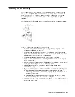
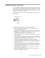
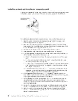
The
following
illustration
shows
how
to
install
the
expansion-card
bracket
on
the
system
board.
To
install
the
expansion-card
bracket,
complete
the
following
steps:
1.
Read
the
safety
information
that
begins
on
page
“Safety”
on
page
v
and
“Installation
guidelines”
on
page
17.
2.
Shut
down
the
operating
system,
turn
off
the
blade
server,
and
remove
the
blade
server
from
the
BladeCenter
unit.
See
“Removing
the
blade
server
from
the
BladeCenter
unit”
on
page
19
for
instructions.
3.
Carefully
lay
the
blade
server
on
a
flat,
static-protective
surface.
4.
Open
the
blade
server
cover
(see
“Opening
the
blade
server
cover”
on
page
20
for
instructions).
5.
If
you
are
installing
a
standard-form-factor
expansion
card
in
the
blade
server
and
a
MPE
unit
or
expansion
unit
is
attached
to
the
blade
server,
remove
the
device
(see
“Removing
an
expansion
unit”
on
page
21).
6.
Locate
SAS
connector
1
(see
“Blade
server
connectors”
on
page
14).
7.
If
a
SAS
drive
is
installed
into
SAS
connector
1,
remove
the
SAS
drive
and
the
drive
tray
(see
“Removing
a
SAS
drive”
on
page
26
and
“Removing
a
SAS
drive
tray”
on
page
24).
8.
Orient
the
expansion-card
bracket
so
that
the
screw
holes
in
the
bracket
are
lined
up
with
the
two
screw
holes
in
front
of
SAS
connector
1
and
closest
to
the
side
of
the
blade
server.
The
flat
side
of
the
expansion-card
bracket
should
be
towards
the
side
of
the
blade
server.
9.
Use
a
screwdriver
to
install
two
screws
into
the
expansion-card
bracket
to
attach
the
tray
to
the
system
board.
10.
If
you
have
other
devices
to
install
or
remove,
do
so
now;
otherwise,
go
to
“Completing
the
installation”
on
page
46.
Chapter
3.
Installing
optional
devices
33
Summary of Contents for LS42 - BladeCenter - 7902
Page 1: ......
Page 2: ......
Page 3: ...BladeCenter LS22 and LS42 Type 7901 and 7902 Installation and User s Guide...
Page 26: ...16 BladeCenter LS22 and LS42 Type 7901 and 7902 Installation and User s Guide...
Page 88: ...78 BladeCenter LS22 and LS42 Type 7901 and 7902 Installation and User s Guide...
Page 89: ......
Page 90: ...Part Number 44R5057 Printed in USA 1P P N 44R5057...

