


Chapter 3. Operating the drive
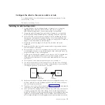
The following indicators on the front panel are used to operate the drive:
v
Single-character display (SCD)
v
SCD dot
v
Ready and Fault status lights
v
Unload button
v
Encryption status light
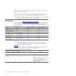
Operating modes
The drive functions in the following modes:
Operation mode
Operation mode functions include reading and writing data, cartridge
manipulation, error reporting, and firmware updating using an FMR
cartridge. For more information, see “Status lights” on page 18.
Maintenance mode
Maintenance mode functions include drive diagnostic, create FMR
cartridge, and drive dump manipulation (force to RAM, copy to tape, copy
to flash memory, and erase flash). For more information, see “Diagnostic
and maintenance functions” on page 23.
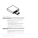
The Unload button is used to switch between modes. For more information, see
“Unload button” on page 20.
Single-character display (SCD)
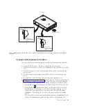
The SCD (see “Front panel of the drive” on page 2) presents a single-character
code for:
v
Error conditions and informational messages
v
Diagnostic or maintenance functions (in Maintenance mode only)
Appendix C, “Error codes and messages,” on page 59 lists the codes for error
conditions and informational messages. If multiple errors occur, the code with the
highest priority (represented by the lowest number) is displayed first. When the
error is corrected, the code with the next highest priority is displayed, and so on
until no errors remain.
“Diagnostic and maintenance functions” on page 23 lists the single-character codes
that represent diagnostic or maintenance functions. To initiate a function, the unit
must be in maintenance mode.
The SCD is blank during normal operation.
SCD dot
If a drive dump is present while the drive is in maintenance mode, a single dot
illuminates in the lower right corner of the SCD (
8
). For information about how
to copy the dump, see “Function code 5: Copy drive dump” on page 29.
© Copyright IBM Corp. 2011
17
Summary of Contents for L5X
Page 2: ......
Page 10: ...viii Half High LTO Gen 5 SAS Tape Drive Installation and User s Guide...
Page 14: ...xii Half High LTO Gen 5 SAS Tape Drive Installation and User s Guide...
Page 16: ...xiv Half High LTO Gen 5 SAS Tape Drive Installation and User s Guide...
Page 58: ...40 Half High LTO Gen 5 SAS Tape Drive Installation and User s Guide...
Page 71: ...Figure 14 RID tag on rear panel Chapter 5 Resolving problems 53...
Page 72: ...54 Half High LTO Gen 5 SAS Tape Drive Installation and User s Guide...
Page 76: ...58 Half High LTO Gen 5 SAS Tape Drive Installation and User s Guide...
Page 90: ...72 Half High LTO Gen 5 SAS Tape Drive Installation and User s Guide...
Page 102: ...84 Half High LTO Gen 5 SAS Tape Drive Installation and User s Guide...
Page 119: ......
Page 120: ...Part Number 60Y1487 Printed in USA 1P P N 60Y1487...


