background image

Configure the drive to the server, switch, or hub

To configure the drive to work with the server, see the documentation for that
server, switch, or hub.

The drive is now ready for use.

Installing an external tape drive

1.

Unpack the drive and store the packaging for future moves or shipping.

Important:

If you return the unit for service, ship it in its original or

equivalent packing material, or the warranty might be invalidated.

2.

Inspect the unit for shipping damage. If there is damage, do not install the
unit. Report the damage immediately by contacting your place of purchase.

3.

Locate the label on the rear panel of the unit with the machine type, model
number, and serial number of the unit. Make a note of these numbers and
store them in an easily accessible place. Should you need to contact Technical
Support, you will be asked for these numbers.

4.

Inspect the power cord plug to make sure that it matches the power
receptacle.

5.

Make sure that all of the associated electrical outlets are grounded and that
the circuit breaker is turned on.

6.

Position the drive so that it is convenient to the server. The only restrictions
are the length of the power cord and the length of the cable to the server. Do
not place anything on top of the tape drive.

7.

If there are no other devices attached to your server, a SAS host adapter card
might need to be installed in the server. To install an adapter, see the
instructions that accompany it, as well as the documentation that came with
your server.

8.

Locate the SAS cable and make sure the tape drive is turned off.

9.

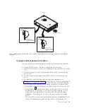
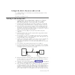
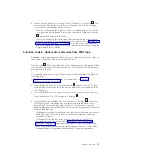
Connect the SAS cable to SAS host adapter and to the tape drive. Although
the tape drive has two SAS ports, it can be connected only to one server. The
following image shows a connection to one server.

10.

Make sure that the host adapter and the server are configured correctly for a
SAS bus operation. See the documentation that came with the host adapter
and your server for instructions.

11.

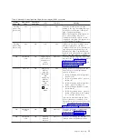
Plug the power cord into the rear panel (see Figure 5 on page 3), then plug the
other end into a grounded electrical outlet.

12.

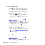
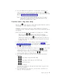
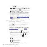
Turn on the unit by pressing the Power button. The POST runs, which checks
all hardware except the drive head. During the POST, the single-character
display (SCD) flashes several segmented characters. Each segmented character
represents a test performed during the POST. When the POST finishes, the
SCD momentarily lights all of the segmented characters and then goes blank.

Chapter 2. Installing

15

Summary of Contents for L5X

Page 1: ...rtant Review the maintenance information in Chapter 3 Operating the drive and in the Warranty information document that comes with the tape drive because periodic maintenance is not covered by the IBM...

Page 2: ......

Page 3: ...IBM Half High LTO Gen 5 SAS Tape Drive Installation and User s Guide Machine Type 3628 Model L5X and N5X...

Page 4: ...on and Environmental Notices and User Guide documents on the IBM Documentation CD and the Warranty information and Important notices documents that come with the product First Edition May 2011 Copyrig...

Page 5: ...Lees voordat u dit product installeert eerst de veiligheidsvoorschriften Ennen kuin asennat t m n tuotteen lue turvaohjeet kohdasta Safety Information Avant d installer ce produit lisez les consignes...

Page 6: ...eia as Informa es sobre Seguran a Antes de instalar este producto lea la informaci n de seguridad L s s kerhetsinformationen innan du installerar den h r produkten iv Half High LTO Gen 5 SAS Tape Driv...

Page 7: ...equipment when there is evidence of fire water or structural damage v Disconnect the attached power cords telecommunications systems networks and modems before you open the device covers unless instru...

Page 8: ...sure DANGER Some laser products contain an embedded Class 3A or Class 3B laser diode Note the following Laser radiation when open Do not stare into the beam do not view directly with optical instrumen...

Page 9: ...s the following label attached Hazardous voltage current and energy levels are present inside any component that has this label attached There are no serviceable parts inside these components If you s...

Page 10: ...viii Half High LTO Gen 5 SAS Tape Drive Installation and User s Guide...

Page 11: ...a tape cartridge 22 Mid tape recovery 22 Cleaning the drive head 23 Cleaning the tape drive 23 Diagnostic and maintenance functions 23 Entering Maintenance mode 25 Exiting Maintenance mode 25 Functio...

Page 12: ...ndix F Notices 77 Trademarks 77 Important notes 78 Particulate contamination 79 Documentation format 79 Electronic emission notices 80 Federal Communications Commission FCC statement 80 Industry Canad...

Page 13: ...ouble boxing tape cartridges for shipping 47 13 Flowchart for analyzing maintenance problems 49 14 RID tag on rear panel 53 15 Leader pin in the incorrect and correct positions 66 16 Placing the dislo...

Page 14: ...xii Half High LTO Gen 5 SAS Tape Drive Installation and User s Guide...

Page 15: ...of status lights and single character display SCD 18 7 Functions that the Unload button performs 20 8 Diagnostic and maintenance functions 24 9 Ultrium cartridge compatibility with Ultrium tape drive...

Page 16: ...xiv Half High LTO Gen 5 SAS Tape Drive Installation and User s Guide...

Page 17: ...s Chapter 5 Resolving problems on page 49 gives tips for solving tape drive problems Appendix A Getting help and technical assistance describes what to do if you experience a problem with your tape dr...

Page 18: ...ion These statements indicate situations that can be potentially hazardous to you A caution statement is placed just before the description of a potentially hazardous procedure step or situation v Dan...

Page 19: ...Drive is the fifth generation in the Ultrium series of products and is available with a Serial Attached SCSI interface SAS This model incorporates the Linear Tape Open LTO IBM Ultrium 5 Half High Tap...

Page 20: ...ystems interface SAS Note Although the tape drive has two SAS ports the drive supports only one host connection The Ethernet port is only used by service personnel v Half height form factor v Native s...

Page 21: ...nal tape drive front panel element descriptions Important 1 The tape drive supports only one host connection 2 The Ethernet port is only used by service personnel Figure 5 External tape drive rear pan...

Page 22: ...tridge and is compatible with the cartridges of its predecessor the IBM Half High LTO Ultrium 4 Tape Drive The drive has the following capabilities and limitations Note To improve system performance t...

Page 23: ...reduces backhitch the condition that occurs when a tape stops reverses and restarts motion A backhitch is usually the result of a mismatch between the data rates of the server and the drive Channel ca...

Page 24: ...ed simultaneously with thinner and longer cables its full duplex signal transmission supports 6 0 Gb second SAS drives can be hot plugged SAS drives will auto negotiate speed There are no configurable...

Page 25: ...048 m 10 000 ft Maximum altitude for shipping 12 192 m 40 000 ft Environmental specifications Environmental factor Operating Storage or Shipping Drive temperature 10 to 40 C 50 to 104 F 40 to 60 C 40...

Page 26: ...m 10 000 ft Maximum altitude for shipping 12 192 m 40 000 ft Environmental specifications Environmental factor Operating Storage or Shipping Drive temperature 10 to 40 C 50 to 104 F 40 to 60 C 40 to...

Page 27: ...e removed covers and other parts in a safe place v Do not attempt to lift an object that you think is too heavy for you If you have to lift a heavy object observe the following precautions Make sure t...

Page 28: ...er s Guide this document the multilingual Safety Information document and the Environmental Notices and User s Guide v SAS cable An internal split SAS cable for the internal drive An external SAS cabl...

Page 29: ...ive has cooled to the operating temperature range less than 40 C or 104 F cool the drive more quickly by applying airflow for 30 minutes Power on the drive and use a diagnostic tape to test it before...

Page 30: ...report the permanent error instead of activating the head brush ERP Mount the drive in an enclosure or server When mounting the drive v Use an appropriate screw length v Make sure that no objects such...

Page 31: ...le turning on the power to the enclosure v During the power on initialization and POST Power On Self Test the SCD briefly displays 8 then becomes blank not lit when POST is complete and there are no P...

Page 32: ...s on the single character display SCD go to Appendix C Error codes and messages on page 59 If no error appears continue to the next step 5 Turn off the enclosure 6 Disconnect the power cord from both...

Page 33: ...length of the power cord and the length of the cable to the server Do not place anything on top of the tape drive 7 If there are no other devices attached to your server a SAS host adapter card might...

Page 34: ...tems support supportsite wss docdisplay lndocid TAPE FILES brandind 5000019 or complete the following steps Note Changes are made periodically to the IBM website The actual procedure might vary slight...

Page 35: ...le character display SCD The SCD see Front panel of the drive on page 2 presents a single character code for v Error conditions and informational messages v Diagnostic or maintenance functions in Main...

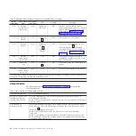
Page 36: ...ting maintenance selection Flashing character Off On Error condition Solid character Off Flashing Power is turned on or a reset is initiated Random segments Off On Note The white Encryption status lig...

Page 37: ...g on the SCD For more information see Function code 9 Display error code log on page 32 and Appendix C Error codes and messages on page 59 On or off On or off Off Displaying random segments then blank...

Page 38: ...s a drive dump in flash memory 1 Power should not be disconnected from the drive until the microcode update is complete The drive indicates that the update is complete by resetting and performing POST...

Page 39: ...tatus light is flashing and fault light is solid see Function code 4 Force a drive dump on page 28 v If the drive is in Operating mode status light is solid or flashing green press and hold the Unload...

Page 40: ...tially ejects grasp the cartridge and remove it Important Always remove an ejected cartridge before reinserting it Whenever you unload a tape cartridge the drive writes any pertinent information to th...

Page 41: ...or 50 uses Cleaning the tape drive Clean the exterior surface of the tape drive with a damp towel If you use a liquid all purpose cleaner apply it to the towel Do not spray cleaner directly on the tap...

Page 42: ...the RS 422 interface Function code 7 Run RS 422 wrap test on page 31 8 Unmake FMR Tape Erases the FMR data on a customer supplied scratch blank data cartridge and rewrite the cartridge memory on the t...

Page 43: ...he preceding step While in Maintenance mode the drive will not accept a cartridge unless the drive requests it The SCD will display a flashing C to indicate a cartridge needs to be inserted Maintenanc...

Page 44: ...Approximate Run Time run Function code F Write performance test on page 34 If the Write performance test fails replace the media and exit Maintenance mode Attention For this test insert only a scratch...

Page 45: ...drive firmware from FMR tape complete the following steps 1 Put the drive in Maintenance mode For instructions see Entering Maintenance mode on page 25 2 Press the Unload button once per second until...

Page 46: ...until the code reappears 3 Press and hold the Unload button for 3 or more seconds then release it to select the function The SCD changes to a flashing C 4 Insert a scratch blank data cartridge that is...

Page 47: ...only compatibility for example Gen 3 media error code P appears in the SCD In either case the tape drive unloads the cartridge and exits Maintenance mode after the cartridge is removed To execute Fun...

Page 48: ...erface wrap test Approximate Run Time 10 seconds per loop Number of Loops This test runs until stopped by pressing the Unload button Function code 6 performs a check of the host interface circuitry an...

Page 49: ...of the circuitry and connector for the RS 422 interface This connector supports the Library Drive Interface LDI and the Automation Drive Interface ADI Before selecting this function attach an LDI or R...

Page 50: ...you inserted a write protected cartridge or the media has read only compatibility for example Gen 3 media error code P appears in the SCD In either case the tape drive unloads the cartridge and exits...

Page 51: ...drive diagnostics and Create FMR tape that require a tape cartridge to be inserted Function code E Test cartridge media Approximate Run Time 15 minutes per loop Total Number of Loops 10 Function code...

Page 52: ...ing the Unload button for 10 seconds Function code F Write performance test Approximate Run Time 5 minutes per loop Total Number of Loops 10 Function code F performs tests to make sure that the drive...

Page 53: ...e diagnostic begins the loop sequence Time the first loop by pressing the Unload button once to stop the diagnostic after the completion of the first loop then record the time it takes for the test to...

Page 54: ...of Loops 10 Function code J performs tests to make sure that the drive can read from and write to tape Once you begin this test the diagnostic begins the loop sequence Time the first loop by pressing...

Page 55: ...e the code in Appendix C Error codes and messages on page 59 To clear the error either turn the power off and then on again or restart the drive by pressing and holding the Unload button for 10 second...

Page 56: ...on page 25 2 Press the Unload button once per second until either P or U appears in the SCD P or U will appear in the SCD to indicate the current setting for post error reporting If you cycle past th...

Page 57: ...r second until the code reappears 3 Exit Maintenance mode if you do not want to change the current setting for post error reporting For instructions see Exiting Maintenance mode on page 25 4 To disabl...

Page 58: ...40 Half High LTO Gen 5 SAS Tape Drive Installation and User s Guide...

Page 59: ...artridge is out of the drive Leader pin The tape is attached to a leader pin behind the cartridge door When the cartridge is inserted into the drive a threading mechanism pulls the pin and tape out of...

Page 60: ...of IBM LTO Ultrium data cartridges include a Linear Tape Open Cartridge Memory LTO CM chip see Figure 9 on page 41 that contains information about the cartridge and the tape such as the name of the ma...

Page 61: ...racks at a time Ultrium 4 WORM Green and silvery gray 800 GB 1 600 GB at 2 1 compression Reads and writes data on 896 tracks 16 tracks at a time Ultrium 3 WORM Slate blue and silvery gray 400 GB 800 G...

Page 62: ...the head insert the cleaning cartridge into the tape load compartment of the drive The cleaning is performed automatically When the cleaning is finished the cartridge is ejected Note The drive will au...

Page 63: ...exist near high current cables or power supplies Such exposure can cause the loss of recorded data or make the blank cartridge unusable v Maintain the conditions that are described in Environmental a...

Page 64: ...ly a recommended shipping container that holds the cartridge securely in its jewel case during transportation Ultrium Turtlecases by Perm A Store have been tested and found to be satisfactory They are...

Page 65: ...ating storing and shipping LTO media Environmental specifications Environmental factor Operating Operational storage1 Archival storage2 Shipping Temperature 10 to 45 C 50 to 113 F 16 to 32 C 61 to 90...

Page 66: ...use a minimum of 4000 oersted peak field over the entire space that the cartridge occupies The tape should make two passes through the field at 90 degree orientation change for each pass to achieve co...

Page 67: ...and the drive is functioning properly refer to Procedure 3 in this chapter Refer to Appendix A in this document before you call IBM Technical Support Then contact IBM Technical Support 1 Refer to the...

Page 68: ...ur System x hardware and options go to http www 03 ibm com systems info x86servers serverproven compat us indexsp html To check the host connections for your drive complete the following steps 1 Make...

Page 69: ...ted in the server and the tape drive 3 Replace the SAS cable if it shows any signs of damage Resolving problems with the tape media To resolve problems that are related to media the drive firmware inc...

Page 70: ...ernal Half High LTO Gen 5 SAS Drive with no line cord 49Y9907 3628N5X SAS cable internal 44E8878 Mini SAS cable external 3 m x 4 plug 39R6532 US line cord 3 ft 10 A 125 V 39M5081 To replace your tape...

Page 71: ...Figure 14 RID tag on rear panel Chapter 5 Resolving problems 53...

Page 72: ...54 Half High LTO Gen 5 SAS Tape Drive Installation and User s Guide...

Page 73: ...by following the troubleshooting procedures that IBM provides in the online help or in the documentation that is provided with your IBM product The documentation that comes with IBM systems also descr...

Page 74: ...r region see http www ibm com services supline products For more information about Support Line and other IBM services see http www ibm com services or see http www ibm com planetwide for support tele...

Page 75: ...server to read TapeAlert flags from a tape drive through the host interface The server reads the flags from Log Sense Page 0x2E See the IBM LTO Ultrium Tape Drive SCSI Reference document for the list...

Page 76: ...58 Half High LTO Gen 5 SAS Tape Drive Installation and User s Guide...

Page 77: ...emperature was exceeded Perform one or more of the following actions v Make sure that the cooling fan is rotating and is quiet If it is not see the documentation that came with your enclosure v Remove...

Page 78: ...drive to copy and read a drive dump use Function code 5 Copy drive dump on page 29 2 Turn the tape drive power off and on then retry the operation that produced the error The error code clears when yo...

Page 79: ...on page 35 If the diagnostic fails replace the tape drive If the diagnostic succeeds replace the cartridges that caused the problem The error code clears when you remove the tape cartridge or place t...

Page 80: ...erwritten Use only a scratch data cartridge to run the test v If the diagnostic fails replace the media v If the diagnostic succeeds clean the drive head see Cleaning the drive head on page 23 and run...

Page 81: ...significantly longer than the Approximate Run Time run Function code F Write performance test on page 34 If the Write performance test fails replace the media and exit Maintenance mode If the drive di...

Page 82: ...that the correct media is being used Data encryption is supported with LTO Ultrium 4 and 5 data cartridges only v Retry the encryption operation with the tape cartridge in another encryption enabled...

Page 83: ...steps 1 Look for signs of cartridge mishandling 2 Use the IBM Leader Pin Reattachment Kit part number 08L9129 to correctly seat the pin 3 Use data recovery procedures to minimize the chance of data l...

Page 84: ...the pin retaining spring clips 3 Press the leader pin gently into the clips until it snaps into place and is firmly seated 4 Close the cartridge door 5 Make sure that there are no gaps in the seam of...

Page 85: ...r possible data recovery Discard the mishandled cartridge Figure 17 Rewinding the tape into the cartridge Reattaching a leader pin The first meter of tape in a cartridge is leader tape Once the leader...

Page 86: ...door open Cartridge manual rewind tool A device that fits into the cartridge hub and lets you wind the tape into and out of the cartridge Leader pins Extra leader pins are included C clips Extra C cli...

Page 87: ...ocedure might affect the performance of the leader pin during threading and unloading operations v Touch only the end of the tape Touching the tape in an area other than the end can damage the tape su...

Page 88: ...rtridge door If necessary grasp the tape and pull gently to unwind it from the cartridge 5 Remove the rewind tool by pulling it away from the cartridge Set the tool and the cartridge aside Figure 20 W...

Page 89: ...ape on the pin will cause the repaired cartridge to fail When the tape is properly centered a 0 25 mm 0 01 in gap exists on both sides of the pin 5 Close the pivot arm of the leader pin attach tool by...

Page 90: ...72 Half High LTO Gen 5 SAS Tape Drive Installation and User s Guide...

Page 91: ...val procedures vary depending on the type of enclosure The following procedure can be used if the enclosure documentation is not available for the specific enclosure type Removing the internal drive T...

Page 92: ...Gently push on the rear panel of the drive to remove the chassis from the cover see Figure 24 on page 75 Figure 23 Removing the screws that secure the cover and internal drive 74 Half High LTO Gen 5 S...

Page 93: ...SAS interface and electrical power from the drive Attention Do not disconnect the internal power cable 2 Press the latch assembly to release the drive 3 Slide the internal drive forward toward the fro...

Page 94: ...Figure 26 Sliding the drive forward 76 Half High LTO Gen 5 SAS Tape Drive Installation and User s Guide...

Page 95: ...BILITY OR FITNESS FOR A PARTICULAR PURPOSE Some states do not allow disclaimer of express or implied warranties in certain transactions therefore this statement may not apply to you This information c...

Page 96: ...vice marks of others Important notes Processor speed indicates the internal clock speed of the microprocessor other factors also affect application performance CD or DVD drive speed is the variable re...

Page 97: ...implementation of appropriate remedial measures to mitigate such environmental contamination Implementation of such remedial measures is a customer responsibility Table 13 Limits for particulates and...

Page 98: ...cables and connectors must be used in order to meet FCC emission limits IBM is not responsible for any radio or television interference caused by using other than recommended cables and connectors or...

Page 99: ...rzustellen sind die Ger te wie in den Handb chern beschrieben zu installieren und zu betreiben Des Weiteren d rfen auch nur von der IBM empfohlene Kabel angeschlossen werden IBM bernimmt keine Verantw...

Page 100: ...f the Voluntary Control Council for Interference VCCI If this equipment is used in a domestic environment radio interference may occur in which case the user may be required to take corrective actions...

Page 101: ...Russia Electromagnetic Interference EMI Class A statement People s Republic of China Class A electronic emission statement Taiwan Class A compliance statement Appendix F Notices 83...

Page 102: ...84 Half High LTO Gen 5 SAS Tape Drive Installation and User s Guide...

Page 103: ...f the UNIX operating system The RS 6000 system among others uses AIX as it s operating system alphanumeric Pertaining to a character set that contains letters numerals and usually other characters suc...

Page 104: ...them into either the ASCII or EBCDIC digital character code bezel Decorative and safety cover bicolored Having two colors bit Either of the digits 0 or 1 when used in the binary numbering system BM o...

Page 105: ...e drive Contrast with data cartridge command A control signal that initiates an action or the start of a sequence of actions compact disc CD A disc usually 4 75 inches in diameter from which data is r...

Page 106: ...of output or throughput or increased machine error rate deserialize To change from serial by bit to parallel by byte detented A part being held in position with a catch or lever device Any hardware c...

Page 107: ...l Correspondence in the form of messages transmitted between user terminals over a computer network e mail See electronic mail EPO Emergency power off EPROM Erasable programmable read only memory EQC...

Page 108: ...um and more adaptable to change than pure hardware circuitry An example of firmware is the Basic Input Output System BIOS in read only memory ROM on a PC motherboard FLASH EEPROM An electrically erasa...

Page 109: ...ID Identifier identifier ID 1 In programming languages a lexical unit that names a language object for example the names of variables arrays records labels or procedures An identifier usually consist...

Page 110: ...enables compatibility between different vendors offerings by ensuring that vendors comply with verification standards The LTO technology is implemented in two formats the Accelis format focuses on fa...

Page 111: ...t is the first generation of its type mega One million of meter In the Metric System the basic unit of length equal to approximately 39 37 inches micro One millionth of microcode 1 One or more micro i...

Page 112: ...is the magnetic field strength in the interior of an elongated uniformly wound solenoid that is excited with a linear current density in its winding of one abampere per 4 centimeters of axial length o...

Page 113: ...ownloaded at no cost from the Adobe Systems home page PROM Programmable read only memory PS Power supply PWR Power R rack A unit that houses the components of a storage subsystem such as the library r...

Page 114: ...signals represents mechanical motion Small Computer Systems Interface SCSI A standard used by computer manufacturers for attaching peripheral devices such as tape drives hard disks CD ROM players prin...

Page 115: ...f operating independently of or asynchronously with a controlling system SUPP Support sync Synchronous synchronize Occurring with a regular or predictable time relationship T tachometer tach A device...

Page 116: ...onveniently as a unit VPD Vital product data The information contained within the tape drive that requires nonvolatile storage used by functional areas of the drive and information required for manufa...

Page 117: ...ng damage 9 cleaning 44 cleaning cartridge 44 description 1 features 2 front view 2 performance 4 rear view 3 removing 73 drive cleaning 23 drive dump copying to tape 29 forcing 28 drive head cleaning...

Page 118: ...RS 422 wrap test 31 S safety 9 SAS bus cables 15 SAS Host connections checking 50 SAS interface 6 external 14 internal cable connection 14 SCSI interface external server connection 14 internal cable c...

Page 119: ......

Page 120: ...Part Number 60Y1487 Printed in USA 1P P N 60Y1487...

Reviews: