Chapter 4. Initializing the RackSwitch
When you supply power to the RackSwitch G8124, the switch initializes
automatically.
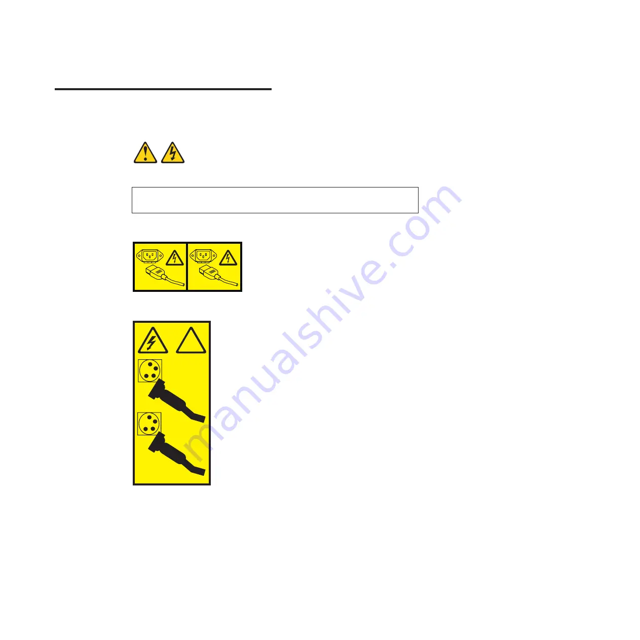
DANGER
Multiple power cords. The product might be equipped with multiple power
cords. To remove all hazardous voltages, disconnect all power cords.
(L003)
1
2
or
!
1
2
The following LEDs indicate the overall system status:
v
Power Supply: Steady green if both power cords are connected, flashing green if
only one power cord is connected.
v
Fan: Steady green if all fans are running, blinking green if there is a fan failure
Use the mini-USB console cable to connect the RS-232 serial port on the switch
unit front panel to a terminal or a computer running a terminal emulation program.
You can access the command-line interface to perform initial configuration tasks.
To access the switch CLI and perform initial configuration tasks, use one of the
following methods:
© Copyright IBM Corp. 2013
43
Summary of Contents for BNT RackSwitch G8124
Page 1: ...IBM System Networking RackSwitch G8124 and G8124 E Installation Guide...
Page 2: ......
Page 3: ...IBM System Networking RackSwitch G8124 and G8124 E Installation Guide...
Page 7: ...DANGER Rack mounted devices are not to be used as shelves or work spaces L002 Safety v...
Page 9: ...Safety vii...
Page 14: ...xii IBM System Networking RackSwitch G8124 and G8124 E Installation Guide...
Page 64: ...48 IBM System Networking RackSwitch G8124 and G8124 E Installation Guide...
Page 72: ...56 IBM System Networking RackSwitch G8124 and G8124 E Installation Guide...
Page 76: ...60 IBM System Networking RackSwitch G8124 and G8124 E Installation Guide...
Page 84: ...68 IBM System Networking RackSwitch G8124 and G8124 E Installation Guide...
Page 87: ......
Page 88: ...Part Number 00AY390 Printed in USA 1P P N 00AY390...


