background image

Connecting the Interface Cables

DANGER

Be sure to read “Safety” on page v before connecting the power
cord.


1

Turn off your PC and all attached devices.

2

Make sure that the monitor stands vertically.

3

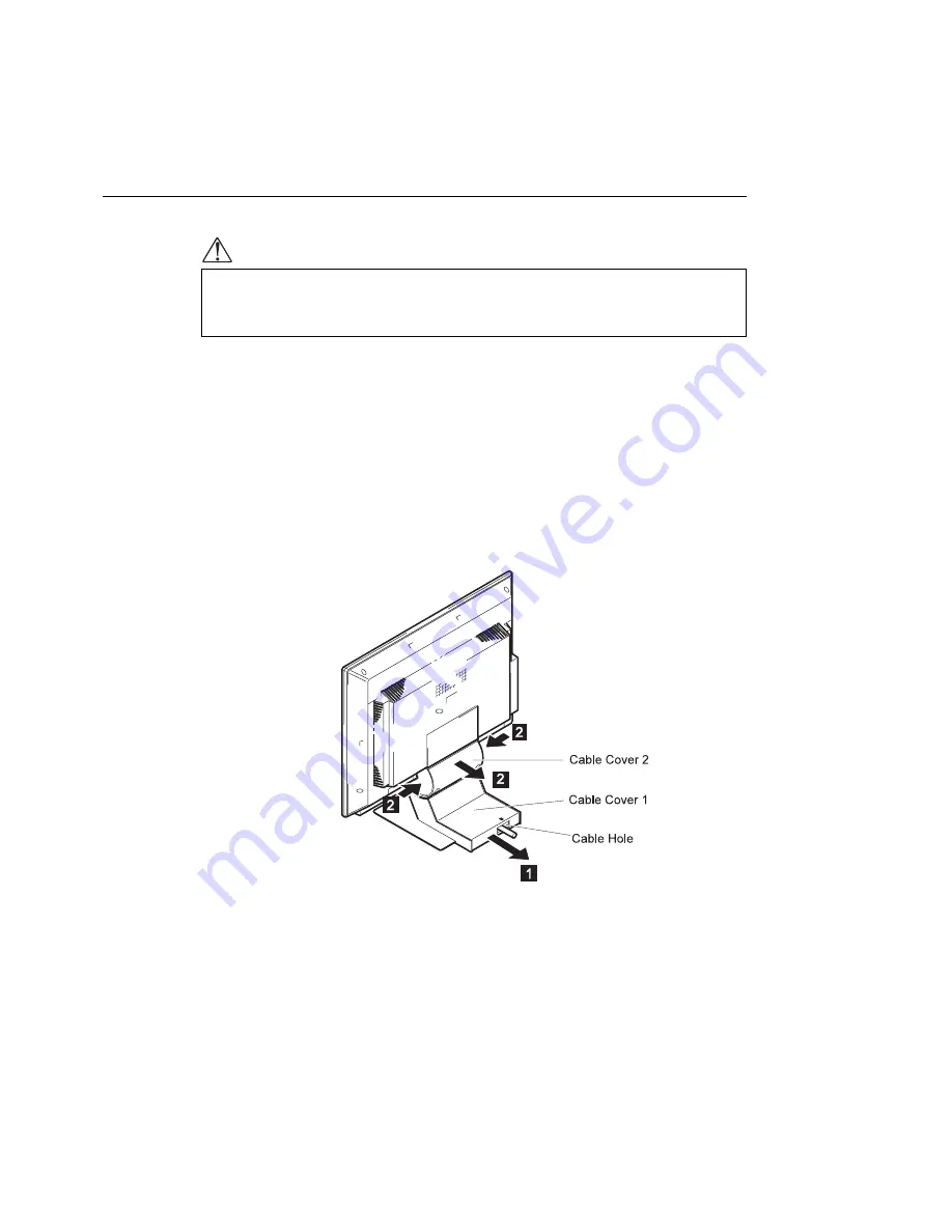
Remove the cable covers at the rear of the monitor.

1

Insert your finger into the cable hole and pull Cable Cover 1.

2

Hold both sides of Cable Cover 2 tightly and pull.


Chapter 1. Setting Up Your Monitor

5

Summary of Contents for 9514-B03

Page 1: ...IBM 9514 B03 or B13 Color LCD Monitor Installation and Operation Guide GA18 7521 00 ...

Page 2: ......

Page 3: ...IBM 9514 B03 or B13 Color LCD Monitor Installation and Operation Guide GA18 7521 00 ...

Page 4: ...cal inaccuracies or typographical errors Changes are periodically made to the information herein these changes will be incorporated in new editions of the publication IBM may make improvements or changes in the products or the programs described in this publication at any time Comments may be addressed to IBM Japan Ltd Yamato Laboratory 1623 14 Shimotsuruma Yamato shi Kanagawa ken 242 Japan IBM ma...

Page 5: ... Configuring Your Monitor Using Automatic Setup 15 Auto Setup for PC DOS 16 Auto Setup for Windows 3 1 Windows 95 Windows NT 19 Auto Setup for OS 2 22 Quick Setup 25 Appendix A The Setup Menus 27 The Setup Main Menu 27 Using the Main Menu 27 Saving Power with Standby Mode 29 The Manual Adjust Menu 30 Using the Manual Adjust Menu 30 Information Menu 33 Appendix B Setting Noninterlace Mode 35 Append...

Page 6: ...iv ...

Page 7: ...ower cord must be disconnected after the telephone line cable In the U K by law the telephone line cable must be connected after the power cord Electrical current from power telephone and communication cables is hazardous To avoid shock hazard connect and disconnect cables as shown below when installing moving or opening the covers of this product or attached devices The power cord must be used wi...

Page 8: ...AUTION The fluorescent lamp in the liquid crystal display LCD contains mercury 50 mg maximum Do not place in trash that is disposed of in landfills Dispose of it as required by local ordinances or regulations CAUTION 1 Do not remove and use the LCD panel separately from its stand 2 Do not lay this monitor in a horizontal position when operating CAUTION Handle this device with care when moving it S...

Page 9: ...eafter called monitor Chapter 1 describes how to set up the monitor and attach it to the personal computer hereafter called PC Chapter 2 describes how to handle and operate the monitor Chapter 3 describes how to configure the monitor to attain the best condition There are four appendixes with additional information Copyright IBM Corp 1997 vii ...

Page 10: ...viii ...

Page 11: ...onitor The LCD screen is fragile and should not be bumped or dropped Lifting the Monitor Carefully remove the monitor from its carton Hold the bottom of the screen with both hands when lifting the monitor Placing the Monitor Before setting up the monitor make sure that there is enough work space around it and a power outlet near it Place the monitor on a hard flat surface Avoid the following condi...

Page 12: ...s Unit DBU Helpline Setup option diskettes AC Adapter and Cable The diskettes contain information used by the Auto Setup program for tuning the monitor performance The monitor operates under standard video software Printed matter IBM 9514 B03 or B13 Color LCD Monitor Installation and Operation Guide this book Warranty 2 ...

Page 13: ...Locations Chapter 1 Setting Up Your Monitor 3 ...

Page 14: ...4 ...

Page 15: ... cord 1 Turn off your PC and all attached devices 2 Make sure that the monitor stands vertically 3 Remove the cable covers at the rear of the monitor 1 Insert your finger into the cable hole and pull Cable Cover 1 2 Hold both sides of Cable Cover 2 tightly and pull Chapter 1 Setting Up Your Monitor 5 ...

Page 16: ...4 Turn the monitor screen face down on a flat surface such as a desk and connect the AC Adapter cable Note Be careful not to damage the screen 5 Thread the AC Adapter cable under the metal hook 6 ...

Page 17: ...nal keyboard mouse cable as shown 1 Disconnect the keyboard cable from your PC then connect it to the keyboard connector at the rear of the monitor 2 Disconnect the mouse cable from your PC then connect it to the mouse connector at the rear of the monitor 3 Connect the keyboard mouse cable P N 83H7859 to the connector at the rear of the monitor Then connect the other end to the keyboard and mouse ...

Page 18: ...s activated c You don t need to use this connection method when you don t reset the display standby mode d You cannot use the keyboard speaker if you use this connection method e You don t need to use this connection method if you are going to use the DPMS function for the standby mode Otherwise go to the next step 8 Turn the monitor upright 9 Fit the cable covers on the monitor 1 Fit cable cover ...

Page 19: ...ur PC 1 Plug in the connector 2 Tighten the screws 11 Connect the power cord to the AC Adapter 12 Connect the other end of the power cord to a correctly grounded ac power source You have finished setting up your monitor Chapter 1 Setting Up Your Monitor 9 ...

Page 20: ...shown in the figure Caring for Your Monitor Be sure to turn off the power before you clean the monitor by doing the following Gently wipe the device covers and the screen with a soft cloth Do not use chemicals such as thinner or benzene They may damage the surface coating 10 ...

Page 21: ...usting the brightness and contrast The Setup Menus Turning On the Monitor To turn on the monitor push and release the power switch To turn it off push and release the switch again Note When you turn off the monitor wait at least 5 seconds before turning it back on again Copyright IBM Corp 1997 11 ...

Page 22: ...hter or the button to make the screen dimmer The brightness value appears on the screen when you push either of these buttons Contrast To adjust the clarity of the screen push the button to increase the contrast or the button to lower the contrast The contrast value appears on the screen when you push either of these buttons 12 ...

Page 23: ...e the functions to optimize the monitor status and to set the power saving mode To display the first setup menu press the setup switch Refer to Chapter 3 for details Here is an example of a setup menu Chapter 2 Operating Your Monitor 13 ...

Page 24: ...14 ...

Page 25: ...our computer 1 If you are going to use full screen on your PC perform the auto setup procedure for PC DOS Go to page 16 2 Perform the auto setup procedure for OS 2 Go to page 22 You do not need to perform the auto setup procedure for Windows Note If your PC does not run with the setup option diskettes shipped with the monitor refer to Quick Setup on page 25 Before you begin the auto setup for your...

Page 26: ... option diskettes are used only for displaying the color bar patterns They are not for changing the display driver 4 Wait about 15 minutes until the monitor warms up Note If the monitor is in standby mode it may automatically turn off while you are waiting for it to warm up Exit standby mode refer to The Setup Main Menu on page 27 5 Display the command prompt screen of the PC DOS full screen displ...

Page 27: ...ontrast control buttons The AUTO SETUP line changes to START and auto setup starts 12 Wait until the PRESS ENTER KEY message is displayed after 10 to 20 seconds 13 Press Enter to start the auto setup procedure The AUTO SETUP line changes to COMPLETED when auto setup is completed The screen may be distorted during setup This is not a problem Chapter 3 Configuring Your Monitor Using Automatic Setup ...

Page 28: ...s repeat the auto setup procedure several times If you still cannot complete the setup adjust it manually by using the manual adjust menu see The Manual Adjust Menu on page 30 or contact your IBM representative 14 Push the setup switch on the bottom of the monitor to turn off the setup main menu You have completed the monitor setup 18 ...

Page 29: ... If you are using some other PC or another video adapter card follow the instructions in the manual shipped with your PC or video adapter card 3 Insert the diskette labeled Setup Option Diskette for DOS Windows into the diskette drive Note The application programs included in the setup option diskettes are used only for displaying the color bar patterns They are not for changing the display driver...

Page 30: ...ove the mouse pointer and the icon bar and tool bar if they are displayed to the bottom center of the screen Otherwise setup might not run properly 8 Push the setup switch on the bottom of the monitor The setup main menu appears 9 Push one of the brightness control buttons to select AUTO SETUP 10 Push one of the contrast control buttons The AUTO SETUP line changes to START and auto setup starts 20...

Page 31: ...on in the table on page 39 Go back to step 8 and redo auto setup If the setup procedure does not complete successfully an AUTO SETUP FAILED message appears In that case repeat the auto setup procedure three times If you still cannot complete the setup adjust manually by using the manual adjust menu see The Manual Adjust Menu on page 30 or contact your IBM representative If after you perform auto s...

Page 32: ... PC change the mode by referring to Appendix B If you are using some other PC or another video adapter card follow the instructions in the manual shipped with your PC or video adapter card 3 Insert the diskette labeled Setup Option Diskette for OS 2 into the diskette drive Note The application programs included in the setup option diskettes are used only for displaying the color bar patterns They ...

Page 33: ...elect AUTO SETUP 10 Push one of the contrast control buttons The AUTO SETUP line changes to START and auto setup starts Wait 10 to 20 seconds Note For better adjustment the color bar pattern should be displayed before the main menu although AUTO SETUP changes to START when the color bar pattern is not display on the screen See Quick Setup on page 25 The AUTO SETUP line changes to COMPLETED when au...

Page 34: ...procedure does not complete successfully an AUTO SETUP FAILED message appears In that case repeat the auto setup procedure three times If you still cannot complete the setup adjust manually by using the manual adjust menu see The Manual Adjust Menu on page 30 or contact your IBM representative If after you perform auto setup the display is still distorted perform the manual setup described in The ...

Page 35: ...You also need a clear contrast between the brightest part of the screen and the darkest for correct adjustment Otherwise the screen may flicker If necessary try to display some other full screen image 4 Push the setup switch on the bottom of the monitor The setup main menu appears 5 Push one of the brightness control buttons to select AUTO SETUP 6 Push one of the contrast control buttons After abo...

Page 36: ...he contrast control button to exit auto setup and go back to step 3 Display another full screen image and redo auto setup If auto setup is not completed after several tries adjust it manually by using the manual adjust menu see The Manual Adjust Menu on page 30 8 Push the setup switch on the bottom of the monitor to turn off the setup main menu 26 ...

Page 37: ...ing functions Auto setup Adjusts the monitor to conform with your PC characteristics and optimizes the monitor status Power saving Saves power by automatically turning off the screen when it is not used Screen size Selects the screen size Brightness control Adjusts the brightness of the screen Contrast control Adjusts the contrast of the screen Using the Main Menu 1 Push the setup switch on the bo...

Page 38: ...u see The Manual Adjust Menu on page 30 The following settings can be set and stored for each screen resolution AUTO SETUP To start auto setup select this item and push one of the contrast buttons START COMPLETED are displayed in sequence until auto setup is complete CONTRAST Adjust contrast This parameter works the same as the contrast adjustment described in Adjusting the Brightness and Contrast...

Page 39: ...nectors at the rear of the monitor The following table shows the power dissipation and the state of indicators when the monitor is in standby mode Mode Power Dissipation Case A DPMS Mode Standby Indicator Power Indicator Case B Normal operation 30 W Max Off On Standby mode 15 W No horizontal sync signal input On On Set time 5 to 60 minutes Power off mode 8 W No vertical sync signal input On On 10 ...

Page 40: ... auto setup Using the Manual Adjust Menu 1 Push and hold one of the brightness control buttons The following menu is displayed 2 Use one of the brightness control buttons to select an item and use one of the contrast buttons to set the values for that item Adjust CLOCK to reduce the vertical stripes 3 Adjust PHASE to reduce the noise on the screen 4 Adjust the display position with H POSI and V PO...

Page 41: ... set values from 0 to 255 BLUE Adjust this parameter to change the blue hue level of the screen You can set values from 0 to 255 COLOR When there are visual noises on the black part of the screen adjust this parameter to suppress it You can set values from 0 to 255 H POSI Adjust this parameter to change the horizontal position of the screen The values you can set depend on your PC V POSI Adjust th...

Page 42: ...u LOAD DEFAULT VALUES Use this parameter to restore all the values in the manual adjust menu to the settings of auto setup If auto setup was not performed the values are restored to the original settings when the monitor was shipped SYSTEM RESET Use this parameter to restore all the values to the original settings when the monitor was shipped 32 ...

Page 43: ... control buttons The following is an example of the information displayed Function Explanation H FREQUENCY The frequency of the video signal horizontal sync signal from your PC V FREQUENCY The frequency of the video signal vertical sync signal or refresh rate from your PC SYNC POLARITY The polarity of the video signal from your PC H stands for the horizontal sync signal and V stands for the vertic...

Page 44: ...34 ...

Page 45: ...1 Turn on the monitor 2 Turn on your PC 3 Press F1 while the message Press F1 for configuration setup is being displayed 4 Select Device and I O in the Device Configuration Utility 5 Select Setup Video 6 Set the display type to Customize and the refresh rate to 60Hz or 75Hz 7 Press ESC three times 8 Select Save and Exit Noninterlace mode has been set Copyright IBM Corp 1997 35 ...

Page 46: ...36 ...

Page 47: ... menu 8 Adjust the CLOCK parameter in the manual adjust menu to suppress the display of vertical stripes 9 To restore all the auto setup or manual adjust menu settings to the original values in effect when the monitor was shipped perform SYSTEM RESET in the manual adjust menu or press each minus button of the brightness and the contrast control simultaneously and turn on the monitor Both LED indic...

Page 48: ...ilm transistors TFTs A small number of missing discolored or lighted dots may be present on the screen which is an intrinsic characteristic of the TFT LCD technology and is not an LCD defect If there is a problem with the LCD contact the DBU Helpline 38 ...

Page 49: ...sync Functions Power saving VESA DPMS Plug Play DDC B Input voltage AC Adapter 100 240 V ac 10 50 60Hz Power dissipation max 30W Power dissipation in power off mode 8W Note This monitor does not support interlace mode or composite sync Type Screen resolution D L Hsync KHz Vsync Hz VGA 640 350 NI 640 450 NI 640 480 NI 29 38 24 38 29 38 69 88 55 88 59 75 720 350 NI 720 400 NI 29 38 29 38 69 88 55 88...

Page 50: ...nd Aptiva series equipped with the following video chips or Matrox Millennium video cards Trident 9680XGI S3 Vision 864 S3 Trio 64V Cirrus GD5446 Cirrus GD5436 ATI 3D RAGE MGA Millennium Matrox Graphics Inc MGA Mystique Matrox Graphics Inc ATI 3D EXPRESSION NEC PC 9800 series computers that support resolutions more than 640 400 and horizontal scan range of 31 5 or more 40 ...

Page 51: ...l adjust menu are saved in the monitor memory Up to 25 settings can be stored Screen Resolution Horiz Vert Timing Clock MHz Hsync KHz Vsync Hz Displayable Dots Horiz Vert 640 400 640 480 720 400 640 480 640 480 800 600 800 600 800 600 800 600 1024 768 1024 768 1024 768 1024 768 25 18 25 18 28 32 31 50 31 50 36 00 40 00 50 00 49 50 65 00 75 00 78 75 80 00 31 47 31 47 31 47 37 86 37 50 35 16 37 88 4...

Page 52: ...42 ...

Page 53: ...roducts except those expressly designated by IBM are the responsibility of the user IBM may have patents or pending patent applications covering subject matter in this document The furnishing of this document does not give you any license to these patents You can send license inquiries in writing to IBM Director of Licensing IBM Corporation 500 Columbus Avenue Thornwood NY 10594 U S A Trademarks T...

Page 54: ...nternational Energy Star Program a U S program that promotes power saving on computer monitors IBM has determined that the IBM 9514 B03 or B13 14 1 inch Color LCD Monitor s built in power saving function conforms to the program standards 44 ...

Page 55: ...tive for help Properly shielded and grounded cables and connectors must be used in order to meet FCC emission limits Proper cables and connectors are available from IBM authorized dealers IBM is not responsible for any radio or television interference caused by using other than recommended cables and connectors or by unauthorized changes or modifications to this equipment Unauthorized changes or m...

Page 56: ...ns du Canada L exploitation faite en milieu résidentiel peut entraîner le brouillage des réceptions radio et télé ce qui obligerait le propriétaire ou l opérateur à prendre les dispositions nécessaires pour en éliminer les causes United Kingdom Office of Telecommunications Statement of Compliance United Kingdom Telecommunications Act 1984 This apparatus is approved under number NS G 1234 J 100003 ...

Page 57: ......

Page 58: ...IBM Printed in Japan GA18 7521 ...

Reviews: