background image

Replacing the system backplane in the 9040-MR9

To replace the system backplane, complete the steps in this procedure.

Procedure

1. Ensure that you have the electrostatic discharge (ESD) wrist strap on and that the ESD clip is plugged

into a ground jack or connected to an unpainted metal surface. If not, do so now.

2. Install the new system backplane.

a) Open the packaging for the new system backplane and place it on an appropriate ESD surface.

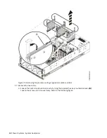
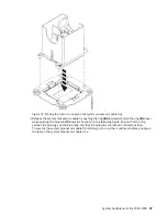
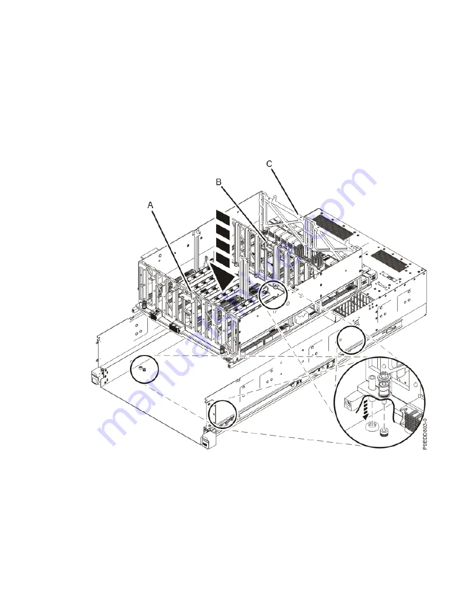
b) Grasp the new system backplane by the front (A) or middle (B) metal bulkheads and the rear

metal bulkhead (C). As you lower the backplane straight down into the chassis, take care to

ensure that the pins on the bottom of the backplane align with the holes in the chassis.

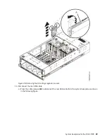
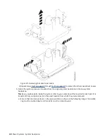
Figure 44. Lowering the system backplane into the chassis

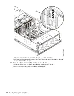
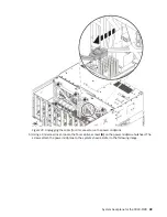
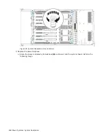
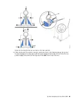
c) Using a 4 mm Hex driver, tighten the four captive screws (A) that mount the backplane to the

chassis. Refer to the following image for the location of the screws.

System backplane for the 9040-MR9   43

Summary of Contents for 9040-MR9

Page 1: ...Power Systems System backplane for the 9040 MR9 IBM...

Page 2: ...G229 9054 and the IBM Environmental Notices and User Guide Z125 5823 This edition applies to IBM Power Systems servers that contain the POWER9 processor and to all associated models Copyright Interna...

Page 3: ...emoving the system backplane 10 Replacing the system backplane 43 Preparing the system for operation 76 Notices 85 Accessibility features for IBM Power Systems servers 86 Privacy policy considerations...

Page 4: ...iv...

Page 5: ...00 300 8751 German safety information Das Produkt ist nicht f r den Einsatz an Bildschirmarbeitspl tzen im Sinne 2 der Bildschirmarbeitsverordnung geeignet Laser safety information IBM servers can use...

Page 6: ...vices To Disconnect 1 Turn off everything unless instructed otherwise 2 For AC power remove the power cords from the outlets 3 For racks with a DC power distribution panel PDP turn off the circuit bre...

Page 7: ...here the air flow is compromised Ensure that air flow is not blocked or reduced on any side front or back of a unit used for air flow through the unit Consideration should be given to the connection o...

Page 8: ...30 mm 30 x 80 in Ensure that all devices shelves drawers doors and cables are secure Ensure that the four leveling pads are raised to their highest position Ensure that there is no stabilizer bracket...

Page 9: ...elves or work spaces Do not place objects on top of rack mounted devices In addition do not lean on rack mounted devices and do not use them to stabilize your body position for example when working fr...

Page 10: ...EC 60825 as a class 1 laser product Consult the label on each part for laser certification numbers and approval information CAUTION This product might contain one or more of the following devices CD R...

Page 11: ...ded for use to assist lift install remove units load up into rack elevations It is not to be used loaded transporting over major ramps nor as a replacement for such designated tools like pallet jacks...

Page 12: ...eleasing winch handle A winch accident could cause serious injury Not for moving humans Make certain clicking sound is heard as the equipment is being raised Be sure winch is locked in position before...

Page 13: ...d DC return DC I design The DC battery return terminal shall not be connected to the chassis or frame ground The dc powered system is intended to be installed in a common bonding network CBN as descri...

Page 14: ...xiv Power Systems System backplane...

Page 15: ...screwdriver System backplane kit 4 mm ball end hex driver Procedure 1 Identify the part and the system that you are working on For instructions see Identifying a part www ibm com support knowledgecen...

Page 16: ...r source from the system by unplugging the power cords from the system Notes This system might be equipped with two or more power supplies If the removing and replacing procedures require the system p...

Page 17: ...or or or or System backplane for the 9040 MR9 3...

Page 18: ...ough to prevent them from interfering with the removal of the system backplane a To unseat the power supply from its position in the system push in the locking tab A b Using the handle B pull the powe...

Page 19: ...rfering with the removal of the system backplane c Repeat steps 8 a on page 5 through 8 b on page 5 to pull out the remaining PCIe adapter cassettes 9 Place your fingers on the indentations and pull t...

Page 20: ...at a time The rack might become unstable if you pull out more than one drawer at a time a If not already removed remove the shipping screws A as shown in the following figure by using a Phillips scre...

Page 21: ...when the system power is turned on might damage the system components a Push the release latches A in the direction shown in the following figure b Slide the cover B off the system unit as shown in t...

Page 22: ...ont as shown in the following figure b Push the system unit back into the rack as shown in the following figure until both release latches of the system unit lock into position Ensure that any cables...

Page 23: ...re When you use an ESD wrist strap follow all electrical safety procedures An ESD wrist strap is used for static control It does not increase or decrease your risk of receiving electric shock when usi...

Page 24: ...the latch A in the following figure and put your index finger against the latch B b Push against the latch with your thumb and then pull out the latch with your index finger This action releases the l...

Page 25: ...e following figure Use a 4 mm ball end hex driver 130 mm long IBM part number 02EA546 to loosen the screws Figure 9 Loosening the disk drive backplane screws c Grasp the disk drive backplane with two...

Page 26: ...out more than one drawer at a time The rack might become unstable if you pull out more than one drawer at a time 1 If not already removed remove the shipping screws A as shown in the following figure...

Page 27: ...the rear of the disk drive backplane as shown in the following figure Press in on the clip to release the cable Hold the disk drive backplane while you remove the SAS cables to prevent the disk drive...

Page 28: ...Figure 12 Unplugging the SAS cables from the base function disk drive backplane 14 Power Systems System backplane...

Page 29: ...Figure 13 Unplugging the SAS cables from the expanded function disk drive backplane f Using two hands fully remove the disk drive backplane from the system System backplane for the 9040 MR9 15...

Page 30: ...Install the system to rail locking clips onto each rail The system to rail locking clips keep the front end of the system from dislodging from the rails when you move the system into the service posi...

Page 31: ...with an L and an R For the right side of the rail ensure that the side stamped R is facing outward Figure 16 Right system to rail locking clip c While holding the blue latch A rotate the clip B into...

Page 32: ...the clip onto the rail d Ensure that the clip C is flush with the rail and that the system chassis pin is seated in the clip as shown in the following figure e Release the blue latch D 18 Power Syste...

Page 33: ...ilizer brackets are not attached to the rack Do not pull out more than one drawer at a time The rack might become unstable if you pull out more than one drawer at a time a If not already removed remov...

Page 34: ...push button A on the trusted platform module card as shown in the following figure Verify that the LED B is lit which indicates that sufficient power exists for the identify LED If the LED B is not li...

Page 35: ...Figure 20 Activating the identify LED 7 Look for the flashing amber LED A of the system backplane Refer to the following image System backplane for the 9040 MR9 21...

Page 36: ...icator LED 8 Remove the SAS cable support A by lifting it straight up as shown in the following figure Then route the cables over the side of the system to keep them out of the way when you remove the...

Page 37: ...Figure 22 Removing the SAS cable support for a base function disk drive backplane System backplane for the 9040 MR9 23...

Page 38: ...he exact location from which they were removed a Unlock the levers A to release the voltage regulator module from its connector Refer to the following image b Rotate the levers in the direction shown...

Page 39: ...mory module riser cards a Open the release latches A on the memory module riser card as shown in the following figure Open the latches to the fully upright 90 degree position b Pull out the memory ris...

Page 40: ...cards 11 Remove the trusted platform module TPM card from location P1 C21 a Grasp the TPM card by the plastic housing Refer to the following image b Pull the TPM card out of its slot on the system ba...

Page 41: ...22 a Unlock the levers A to release the voltage regulator module from its connector Refer to the following image b Rotate the levers in the direction shown c While holding the voltage regulator module...

Page 42: ...ocation P1 C23 a Unlock the levers A to release the voltage regulator module from its connector Refer to the following image b Rotate the levers in the direction shown c While holding the voltage regu...

Page 43: ...e I O voltage regulator module 14 Disconnect the rear USB cable a Press the cable release A to disconnect the rear USB cable from the system backplane as shown in the following figure System backplane...

Page 44: ...the system to prevent it from interfering with the removal of the system backplane 15 Remove the vital product data VPD card from location P1 C24 a Grasp the VPD card by the plastic housing Refer to t...

Page 45: ...r Refer to the following image b Rotate the levers in the direction shown c While holding the voltage regulator module or filler by its levers pull upward to remove the voltage regulator module or fil...

Page 46: ...ulator modules or fillers 17 Remove the heat sinks a Loosen the heat sink actuation screw by turning the supplied hex key counterclockwise A Loosen the screw until it moves freely Refer to the followi...

Page 47: ...tweezers to remove the thermal interface material TIM from the system processor module Discard the TIM after you remove it Important The TIM cannot be reused The replacement system backplane kit inclu...

Page 48: ...t be turned inward Figure 34 Ensuring that the removal tool is in the open position e Align the tool over the system processor module Ensure that the beveled edge on the tool aligns with the beveled e...

Page 49: ...ng A slightly so that the blue tabs B snap outward and the jaws engage with the system processor module as shown in the following figure Make sure that both of the tool jaws are locked onto the system...

Page 50: ...oes not disengage and fall back into the socket of the system processor module If the system processor module falls back into the socket of system processor module the pins might be damaged Place the...

Page 51: ...n while pushing the blue tabs C inwards as shown in the following figure Ensure that the ring catches the openings on the blue tabs and that the blue tabs are locked in a fixed position To prevent the...

Page 52: ...dule from the tool j Repeat steps 18 a on page 33 through 18 i on page 37 to remove all of the system processor modules 19 Remove the power midplane a Unplug the cable from its connector on the power...

Page 53: ...nector on the power midplane b Using a 4mm Hex driver loosen the four captive screws A on the power midplane bulkhead The screws attach the power midplane to the system chassis Refer to the following...

Page 54: ...ning the captive screws on the power midplane bulkhead c Using a 4mm Hex driver loosen the four thumbscrews B that secure the power midplane to the metal brackets inside the system 40 Power Systems Sy...

Page 55: ...ystem Refer to the previous image e Place the power midplane on an appropriate ESD surface 20 Remove the system backplane a Using a 4 mm Hex driver loosen but do not remove the four captive screws A t...

Page 56: ...le B metal bulkheads and the rear metal bulkhead C Lift straight up to disengage the four alignment pins from the bottom of the chassis Figure 43 Grasping the system backplane and disengaging the pins...

Page 57: ...ystem backplane and place it on an appropriate ESD surface b Grasp the new system backplane by the front A or middle B metal bulkheads and the rear metal bulkhead C As you lower the backplane straight...

Page 58: ...5 System backplane screw locations 3 Replace the power midplane a Grasp the power midplane by its bulkhead A and lower it into the system chassis Refer to the following image 44 Power Systems System b...

Page 59: ...ptive thumbscrews B on the power midplane bulkhead Refer to the previous image c Using a 4mm Hex driver tighten the four captive screws C so that the power midplane bulkhead is securely attached to th...

Page 60: ...Figure 47 Tightening the captive screws on the power midplane bulkhead d Reconnect the cable to its connector on the power midplane 46 Power Systems System backplane...

Page 61: ...r module sockets on the new system backplane a Grasp the latches on both sides of the socket dust cover and squeeze them inwards until the latches release from the pins on the system backplane b Lift...

Page 62: ...in the new system backplane Tip As you replace parts inside the system refer to your notes about the location for each part It is important that you replace parts in the exact location from which the...

Page 63: ...er the system processor module as shown in the following image Ensure that the beveled edge on the tool aligns with the beveled edge of the processor Ensure that the two guide pins A are inserted into...

Page 64: ...ing A slightly so that the blue tabs B snap outward and the jaws engage with the system processor module C as shown in the following figure Make sure that both of the tool jaws are locked onto the sys...

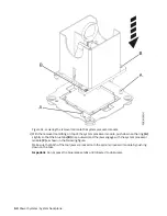
Page 65: ...r on the socket Align the guide pins A with the alignment holes B on each side of the tool Use care to lower the tool evenly without tilting the tool Refer to the following figure Note Do not attempt...

Page 66: ...m processor module f Open the latches that hold the system processor module in the supplied removal tool A as shown in the following figure Push down on the ring B while pressing in on the tabs C 52 P...

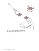
Page 67: ...protective film from the clear carrier strip by using the supplied tweezers Note The TIM must remain flat Small wrinkles are acceptable but folds are not acceptable c Using the tweezers remove the TI...

Page 68: ...Figure 55 Installing the silver colored TIM onto the processor d Place the heat sink on the TIM as shown in the following figure 54 Power Systems System backplane...

Page 69: ...following figure f Tighten the center load screw clockwise by using the supplied hex key as shown by B in the following figure until a firm stop is reached If the heat sink moves noticeably the load a...

Page 70: ...ginal system backplane The socket dust covers protect the sockets during shipping a Lower the socket dust cover over one of the sockets on the system backplane and ensure that the holes B on the socke...

Page 71: ...A in the open position hold the voltage regulator module or filler by its levers and lower the voltage regulator module or filler into its slot in the system Refer to the following image b Gently pus...

Page 72: ...s or fillers 9 Replace the vital product data VPD card in location P1 C24 a Align the VPD card in its slot on the system backplane Refer to the following image b Press the VPD card firmly into place u...

Page 73: ...Figure 60 Replacing the VPD card 10 Reconnect the rear USB cable A in the USB socket on the system backplane as shown in the following figure System backplane for the 9040 MR9 59...

Page 74: ...en position hold the voltage regulator module by its levers and lower the voltage regulator module into its slot in the system Refer to the following image b Gently push the voltage regulator module i...

Page 75: ...d the voltage regulator module by its levers and lower the voltage regulator module into its slot in the system Refer to the following image b Gently push the voltage regulator module into its connect...

Page 76: ...dule 13 Replace the trusted platform module TPM card in location P1 C21 a Insert the TPM card into its slot on the system backplane Refer to the following image b Push the TPM card into place until it...

Page 77: ...wing figure b Align the memory module riser card with the connector c Press the memory module riser card firmly into the connector d Rotate the release latches into the closed position and press the r...

Page 78: ...s and lower the voltage regulator module into its slot in the system Refer to the following image b Gently push the voltage regulator module into its connector c Rotate the levers in the direction sho...

Page 79: ...your fingers holding the SAS cables against the foam lower the SAS cable support B and SAS cables straight down between the alignment pins C The foam holds the cables against the side of the system an...

Page 80: ...Figure 67 Replacing the SAS cable holder 17 Route the SAS cables around to the front of the system 66 Power Systems System backplane...

Page 81: ...il locking clip from the left rail 19 Complete the following steps to place the system in the operating position a Unlock the blue rail safety latches A by lifting them upward as shown in the followin...

Page 82: ...two hands grasp the disk drive backplane where indicated by the blue squares in the following figure Partially insert the disk drive backplane straight into the front of the system Do not yet fully in...

Page 83: ...the disk drive backplane b Move the system unit A to be at most 20 3 cm 8 in from the rack as shown in the following figure Ensure that any cables do not catch or bind as you move the system System b...

Page 84: ...ends of the SAS cables attach the SAS cables to the rear of the disk drive backplane as shown in the following figure Hold the disk drive backplane while you attach the SAS cables to prevent the disk...

Page 85: ...Figure 72 Attaching the SAS cables to the base function disk drive backplane System backplane for the 9040 MR9 71...

Page 86: ...AS cables to the expanded function disk drive backplane d Again using two hands push the disk drive backplane back into place ensuring that the alignment pins at A insert into the slots at B 72 Power...

Page 87: ...rive backplane e Push the system unit A back into the rack until both release latches of the system unit lock into position Ensure that any cables do not catch or bind as you push in the system System...

Page 88: ...he screws First set the screw threads on one side then the other Then evenly tighten the screws on both sides until both sides are seated If you screw in one side of the disk drive backplane completel...

Page 89: ...he bottom of the fan push the fan into its slot as shown in the following figure c Push the fan handle in the direction that is shown in the following figure d Push against the left front of the blue...

Page 90: ...ctrostatic discharge ESD wrist strap on and that the ESD clip is plugged into a ground jack or connected to an unpainted metal surface If not do so now 2 Complete the following steps to place the syst...

Page 91: ...u pull out the system Figure 78 Placing the system in service position 3 Replace the service access cover a Lower the cover A onto the system unit Ensure that the cover alignment pins C on each side o...

Page 92: ...ont as shown in the following figure b Push the system unit back into the rack as shown in the following figure until both release latches of the system unit lock into position Ensure that any cables...

Page 93: ...e front cover Position the cover A on the front of the system unit as shown in the following figure so that the four pins B on the system match the four holes at the rear of the cover Press the tabs C...

Page 94: ...e open the rack door at the rear of the system 7 Replace the power supplies a Slide the power supply into the system until the latch locks in place b Repeat step 7 a on page 80 to replace the remainin...

Page 95: ...ter cassettes a Slide the PCIe adapter cassette forward until the cassette is fully seated b To lock the cassette in its slot squeeze the latch lever A toward the latch B and rotate the latch B in the...

Page 96: ...settes 9 Using your labels reconnect all of the external cables that plug into the PCIe adapters 10 Using your labels reconnect the power cords A to the system unit as shown in the following figure Fa...

Page 97: ...m support knowledgecenter POWER9 p9haj crustartsys htm 14 Verify the installed part If you replaced the part because of a service action verify the installed part For instructions see https www ibm co...

Page 98: ...84 Power Systems System backplane...

Page 99: ...ct s and or the program s described in this publication at any time without notice Any references in this information to non IBM websites are provided for convenience only and do not in any manner ser...

Page 100: ...vision to use information technology content successfully Overview The IBM Power Systems servers include the following major accessibility features Keyboard only operation Operations that use a scree...

Page 101: ...ftware Offering does not use cookies or other technologies to collect personally identifiable information If the configurations deployed for this Software Offering provide you as the customer the abil...

Page 102: ...s authority to operate the equipment This device complies with Part 15 of the FCC rules Operation is subject to the following two conditions 1 this device may not cause harmful interference and 2 this...

Page 103: ...t explains the JEITA statement for products greater than 20 A single phase This statement explains the JEITA statement for products greater than 20 A per phase three phase Electromagnetic Interference...

Page 104: ...Klasse A Ger te m ssen mit folgendem Warnhinweis versehen werden Warnung Dieses ist eine Einrichtung der Klasse A Diese Einrichtung kann im Wohnbereich Funk St rungen verursachen in diesem Fall kann...

Page 105: ...pment into an outlet on a circuit different from that to which the receiver is connected Consult an IBM authorized dealer or service representative for help Properly shielded and grounded cables and c...

Page 106: ...t wattage compliance This statement explains the Japan Electronics and Information Technology Industries Association JEITA statement for products less than or equal to 20 A per phase This statement ex...

Page 107: ...republik Deutschland Zulassungsbescheinigung laut dem Deutschen Gesetz ber die elektromagnetische Vertr glichkeit von Ger ten EMVG bzw der EMC Richtlinie 2014 30 EU f r Ger te der Klasse B Dieses Ger...

Page 108: ...property contained therein IBM reserves the right to withdraw the permissions granted herein whenever in its discretion the use of the publications is detrimental to its interest or as determined by...

Page 109: ......

Page 110: ...IBM...

Reviews: