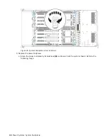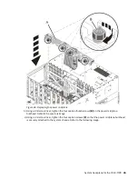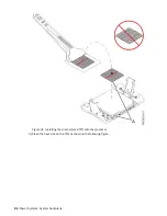
Figure 42. System backplane screw locations
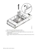
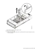
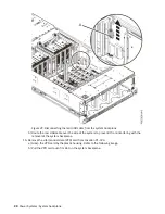
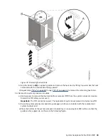
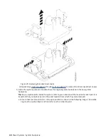
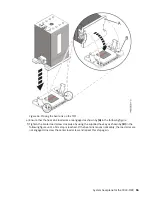
b) Grasp the system backplane by the front (A) or middle (B) metal bulkheads and the rear metal
bulkhead (C). Lift straight up to disengage the four alignment pins from the bottom of the chassis.
Figure 43. Grasping the system backplane and disengaging the pins
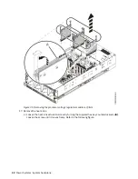
c) Place the system backplane on an appropriate ESD surface.
42 Power Systems: System backplane
Summary of Contents for 9040-MR9
Page 1: ...Power Systems System backplane for the 9040 MR9 IBM...
Page 4: ...iv...
Page 14: ...xiv Power Systems System backplane...
Page 17: ...or or or or System backplane for the 9040 MR9 3...
Page 98: ...84 Power Systems System backplane...
Page 109: ......
Page 110: ...IBM...

