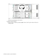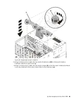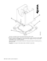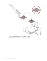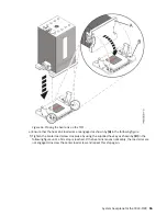
Figure 57. Tightening the center load screw on the heat sink
g) Repeat steps “6.a” on page 53 through “6.f” on page 55 to install new TIM and the new heat sinks
on the remaining system processor modules.
7. Install the socket dust covers on the original system backplane.
The socket dust covers protect the sockets during shipping.
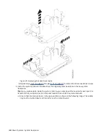
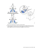
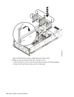
a) Lower the socket dust cover over one of the sockets on the system backplane and ensure that the
holes (B) on the socket dust cover align with the two guide pins (A) on the system backplane. Push
straight down until the latches (D) on the socket dust cover engage with the latches (C) on the
backplane. Refer to the following figure.
56 Power Systems: System backplane
Summary of Contents for 9040-MR9
Page 1: ...Power Systems System backplane for the 9040 MR9 IBM...
Page 4: ...iv...
Page 14: ...xiv Power Systems System backplane...
Page 17: ...or or or or System backplane for the 9040 MR9 3...
Page 98: ...84 Power Systems System backplane...
Page 109: ......
Page 110: ...IBM...


