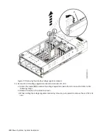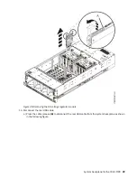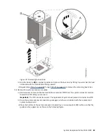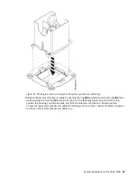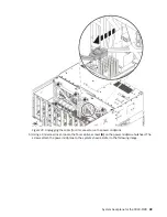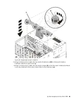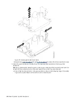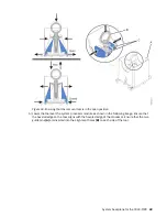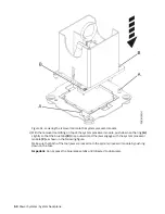
Figure 41. Loosening the thumbscrews and removing the power midplane
d) Lift the power midplane by its bulkhead (C) and pull it out of the system. Refer to the previous
image.
e) Place the power midplane on an appropriate ESD surface.
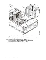
20. Remove the system backplane.
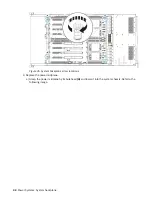
a) Using a 4 mm Hex driver, loosen but do not remove the four captive screws (A) that mount the
backplane to the chassis. Refer to the following image for the location of the screws.
System backplane for the 9040-MR9 41
Summary of Contents for 9040-MR9
Page 1: ...Power Systems System backplane for the 9040 MR9 IBM...
Page 4: ...iv...
Page 14: ...xiv Power Systems System backplane...
Page 17: ...or or or or System backplane for the 9040 MR9 3...
Page 98: ...84 Power Systems System backplane...
Page 109: ......
Page 110: ...IBM...


