


5.
Select
the
desired
post
option
(short,
tall,
or
both)
that
you
want
to
install.
To
combine
both
posts
for
additional
display
height,
press
the
eight-tabbed
post
end
into
the
non-tabbed
end
of
the
other
post.
The
upper
post
can
be
either
the
short
post
or
the
tall
post.
Line
up
the
rib
F
of
one
post,
as
shown
in
the
following
figure,
into
the
slot
of
the
other
post.
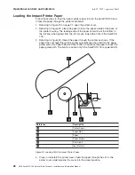
6.
Locate
the
customer
display
cable
G
and
insert
the
smaller
of
the
two
customer
display
cable
connectors
B
through
the
bottom
of
the
slot
E
on
the
base
of
the
SurePOS
chassis
up
through
assembled
post
option
D
and
the
display
yoke
C
.
Insert
the
connector
into
the
socket
in
the
display
head
A
.
A
C
E
D
F
B
G
Reference
Description
A
Display
Head
B
Connector
C
Display
Yoke
D
Post
Option
E
Slot
F
Rib
G
Customer
Display
Cable
Figure
7.
Customer
Display
Tower
Installation
Instructions
July
27,
2007
-
Approval
Draft
14
4613
SurePOS
100
Point-of-Sale
Terminal:
Installation
and
Operation
Manual
Summary of Contents for 4613 SurePOS
Page 2: ......
Page 65: ...IBM IBM GA27 4004 GA27 4004 July 27 2007 Approval Draft Appendix D Safety information 53 ...
Page 81: ......


