background image

1

2

3

4

5

6

7

8

A

B

C

D

8

7

6

5

4

3

2

1

D

C

B

A

MODEL NAME

FILE NO.

REV

HYT Science & Technology Co., Ltd

PART NAME

DRAWN BY

CHECKED

APPROVAL

PAGE

OF

DATE

Q0101

M06

Q0103

M04

R0103

10K

C0101

1uF poly

CR0101

A01

VR0104

5.1V

S0102

R0102

47K

R0126
2.7K

R0109 47K

R0108 47K

R0107

2.7K

R0111

47K

R0110
47K

R0101
47K

Q0107

M04

R0112
47K

R0127

1.5K

R0128
2.7K

R0130

10K

R0129
470

VR0101

5.1V

CR0104
N04

Q0108

M04

Q0106

M06

S0101-2

+5VD

+9VD

R0117

10K

R0115

10K

U0107B

4011

U0107C

4011

U0107A

4011

C0104

10uF

U0102A

TA75W01FU

U0103A

4011

Q0109

M04

R0113 10K

R0114
100/NU

R0141
10K

R0140
10K

R0131
10K

R0116 47K

C0105

10uF

C0102

10uF

+9VD

R0104

10K

R0138

56k

C0118

0.33u

C0117

0.33u

C0120

0.33u

C0110

0.33u

C0183

2.2uF

U0102B

TA75W01FU

R0118 100K

C0107 NC

U0104A

4066

U0104B

4066

U0104C

4066

VAG

+2V5

+2V5

+2V5

U0103B

4011

U0103C

4011

U0103D 4011

8

7

6

5

4

3

2

1

15

9

10

11

12

13

14

J0102 (Main)

DB15/F 3ROWS

8

7

6

5

4

3

2

1

15

9

10

11

12

13

14

J0103 (ACC)

DB15/F 2ROWS

VAG SRC

S0101-1

S0101-3

S0101-4

VR0107

5.1V

CR0103

M76

VR0106

5.1V

S0101-8

S0101-6

S0101-5

S0101-7

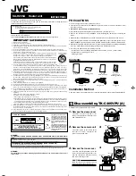
TR-800 REPEATER INTERFACE COMMUNICATION & DISPLAY UNIT

1. Pin assignments for J2 and J4 are identical.

2. All voltages are DC and measured with Hi-Z DMM.

3. S2 and all sections of S1 are shown "OFF".

S0101-10

4. Voltages shown are Inactive/Active state.

"P" after a voltage means pulsed(not continuous).

U0102 Vss

TR-800

Repeater Interface Communication &

H.D Xu

1

1

Aug, 2008

04

DE-BOUNCE

SETUP/

AUDIO PROCESS

CONTROL BUS

Q0110

2N05

8

7

6

5

4

3

2

1

9

10

11

12

13

14

15

TxD

RxD

MIC+

MIC-

Rx Audio

AUX5 I/O

AUX4 I/O

AUX3 I/O

H.R Output

H.R Input

DI

DEO

GND

Switch B+

Ign Control

J0104 (Slave)

DB15/F 3ROWS

TP0101

TP0110

TP0111

TP0109

TP0102

TP0103

TP0104

TP0107

TP0108

TP0106

TP0113

TP0105

TP0112

CR0102

ORG

R0125
1.2K

R0142

4.7K

R0143 10K

R0124
4.7K

C0123
470p

C0112

470p

C0124
0.01u

Q0116

A13

Q0105

DT114

Q0111
DT114

VR0103

5.1V

VR0105
5.1V

R0123

47K/NU

R0122
4.7K/NU

Q0104

DT114/NU

+5VD

R0106

47K

R0105
4.7K

C0103
470p

Q0102
DT114

+5VD

VR0102

5.1V

TP0114

U0107D

4011

PTT

J0107 MIC

J0106 MIC

6--10mV RMS 60% Dev

ACC AUDIO

120mV RMS 60% Dev

SET/O

ME

S0101-9

RPT OUT

OPT OUT

FNT_MIC

ME

OPT/O

RPT/O

SET/O

SET/I

SET/O

SET/I

OPT/O

RPT/O

KNOCKDOWN

C0152

1000p

C0156

1000p

C0153

1000p/NU

C0154

1000p

C0155

1000p

C0151

1000p

R0195 1K

C0157

1000p

6

5

4

3

2

1

7

8

9

10

11

ME

MIC

GND

REST

TxD

RxD

GND

PSW

SB

SP1

SP2

J0106 (Main)

11PIN 1ROW

6

5

4

3

2

1

7

8

9

10

11

ME

MIC

GND

REST

TxD

RxD

GND

PSW

SB

SP1

SP2

J0107 (Slave)

11PIN 1ROW

C0169

1000p

C0166

1000p

C0167

1000p/NU

C0168

100p

C0170

1000p

C0163

100p

C0164

100p

C0165

100p

C0162

1000p

VR0108

02D

L0101

1uH

L0102

1uH

C0160

10uF/16V

R0198

100K

C0161
0.01u

R0197 220K

Vin

3

GND

2

Vout

1

U0109

7809

Vin

3

GND

2

Vout

1

U0108

7805

C0141

10uF/10V

C0147

10uF/16V

C0128

15uF/6.3V

C0130

0.01u

C0148

470p

C0129

22uF/6.3V

C0143

0.01u

C0149

0.01u

R0146
10K

R0147
10K

C0127
15uF/6.3V

4

3

2

1

5
6
7
8

SP1

HOOK/RxD

MIC

ME

PTT/TxD

GND

PSB

SP2

J0109

FNT_RJ45

OP AMP +9V DC
POWER SUPPLY

Vin

3

GND

2

Vout

1

U0101

421C

R0148

1K

R0149

1K

R0172

1K

R0173

1K

R0174

1K

R0175

1K

R0145

100K

R0144
0/NU

PB01

MONI

PB02

SCAN

PB03

UP

PB04

DN

PB05

RPT

PB06

OPT

R0155

47K

R0154

47K

R0153

47K

R0152

47K

R0151

47K

R0150

47K

C0125

0.022u/NU

CR0114

CR0107

CR0113

CR0108

Q0119
DT14

Q0118

2S32

R0177
4.7K

R0171

10K

R0170 0

R0169
100 .5W

R0193 2.2 .5W
R0194 2.2 .5W

SP1

SP2

J0111

Int_Spkr

C0150

1000p

C0144

470p

Q0121

DT14

R0192

330

CR0110

BLU

R0178

0

R0179

1K

R0180

1K

R0181

0

R0182

0

R0183

0

R0184

0

SET/O
OPT/O
RPT/O

FNT_MIC

R0159
4.7K

R0160 47K

R0157 5.6K

R0158 0

C0133

68p

C0134

0.01u

C0131

22p

C0132

22p

L0103

601S

Q0112

2S24

X01

9.8304M

H

z

K02 ENCODE

RESET

1

2

3

4

5

6

7

8

J0110 LCD Module

R0161

47K

C0135

0.01u

C0136

0.01u

R0162
47K

R0163
1K

LAM

P

LCD LCDCS LCDR LCDW LCDCK E 5V

Q0113

2S41

Q0114

DT14

R0166

27K

R0165

27 .5W

C0139

470p

C0137

470p

C0138 470p

R0185

0

R0186

0

R0187

47K

R0188

47K

R0189

47K

R0190

47K

D0112
H23

D0113

H23

D0114

H23

D0115

H23

D0116

H23

D0117

H23

RLED
GLED

C0146

470p

Q0120

DT14

R0191
330

CR0109

BLU

C0145

470p

Q0117

DT14

R0168

330

CR0106

RED

C0140

470p

Q0115

DT14

R0167

180

CR0105
GRN

C0126

470p

GLED
RLED

RPT/O
OPT/O

F0101
0.5A

+2V5

+13V8

+9VD

+13V6

DIG_GND

GND
RESET

SI/RXD
VDD
SO/TXD
VPP
SCK
H/S
CLK
VDE

J0112

REC

RESET

DGND

VDD

SO/TXD

VPP

R0199

0

R1100

0/NU

SO10

RxD

H/S

CLK

+5VD

SETUP/O

28

HOOK/RxD0

29

TxD0

30

SDA

31

SCL

32

PTT

33

TxD1

27

RxD1

26

SPSW

25

AFTST

24

EVdd

23

AVref

1

AVss

2

IC(Vpp)

3

VDD

4

Vss

5

X1

6

X2

7

RESET

8

XT1

9

XT2

10

SHIFT

11

INT

12

RxD2

13

TxD2

14

RSW0(DN)

15

RSW1(UP)

16

LCDBL

17

LCDCS

18

LCDSOD

19

LCDDAT

20

LCDCLK

21

EVss

22

MONI

44

SCAN

43

UP

42

DN

41

RPT/I

40

OPT/I

39

SETUP/I

38

Rx Carrier/I

37

KEYBL

36

RPT/O

35

OPT/O

34

U0110

uPD78KS

SET/I

SET/I

R1101

0

D0118

H23

L0105

601S

RxD

SO/TxD

SO10

VDD

Vpp

CLK

RESET

H/S

Display Unit Board

RV0104

4.7K

PTT/I

PTT/O

PTT_O

PTT/O

PTT/I

PTT/I

PTT/I

R0176

0

PTT_O

D0119

H23

R1103

0

CR0111

CR0112

L0106

601S

C0171

100p

R0164

0

C0158

10uF/16V/NU

Q0122

2S43/NU

R0196

100K/NU

R1102

0/NU

/NU

/NU

NU

VDE

VDE

+5VA

+5VA

R1104 6.8K

R1105 47K

+5VD

5/.1VP

.1/4.8v

.5/8.8v

8.8/.1V

4.8/.1V

.7/.1v

.1/4.3v

4.9/.1V

.1/4.8v

5/0V

0/5V

1

2

3

4

J0113 Jumper

SP2

SP1

C0172

0.33u

R1106

100K

C0176

1000p/NU

C0175

1000p

R1109 0

R0121

39K

R1111 47K

R1112 47K

LOGIC RELAY

R1113

0

KR00

G5V-2

Q0123

M04

R1114

4.7K

1

13

2

3

4

5

9

8

6

1

2

3

6

5

1

2

3

5

6

4

8

9

10

13

12

11

13

12

11

8

9

10

6

5

4

1

2

3

4

13

6

8

11 9

1

16

R1115

0

Q0124

M04

R1118

4.7K

2

9

10

1

5&6

KR03

G5V-1

+9VD

U0104D

4066

10

11

12

R1119 4.7K

R1120

10K

+2V5

C0108

0.33u

R1122 0/NU

R1123

0/NU

R1124

15K

R0169
100.5W

SDA

SCL

SCL

SDA

R1129

4.7K

RESET

SDA

C0177

0.1U

+5V

CR0115

TIL113

1
2

J0113
IN_DCLight

R1130

1.2K

R1132
1.8K

+5V

BCD_

1

BCD_

2

BCD_

3

BCD_

4

BCD_1

BCD_2

BCD_3

BCD_4

VI1

1

VO1
VO2
VI2
VDD
LD
CK
DT
VI3
VO3
VO4
VI4

12

VI5

13

VO5

VO6

VI6

DO

VREF

RESET

GND

VI7

VO7

VO8

VI8

24

U0115

M62364FP

R1134

47K

R1133
NC

Q0126

DT114

+5VD

1

13

3

5

2

4

R1135

6.8k

C0178

2.2uF

U0113A

TA75W01FU

R1136 33K

C0179 NC

2

3

VAG

R1137
NC

+2V5

U0112C

4066

9

8

6

R1138

10K

+2V5

U0112D

4066

10

11

12

R1139
10K

+2V5

LD

CK

DT

DT

CK

LD

+5VD

R1141

1K

R1140

1.2K

C0180

47U 6.3V

+5VD

R1142

0

R1144

0

R1143

0

R1145

4.7K

R1146

1K

R1147

NC

R1148

1K

R1149

1K

R1150

1K

R1151

1K

R1127 15k

R1128 33k

R1125 15K

R1126 33k

7

U0113B

TA75W01FU

R1152

33K

C0182 NC

6

5

VAG

C0111

0.33u

R1154

0

R1153

0

R1155

0

R1156

0

INT

R1159

0

R1158

0

R1157

0

R1160

0

INT

R1161
47K

Q0125

DT114

+5VD

AUX5_1

AUX5_2

AUX5_1

AUX5_2

R1039

39K

R1162 NC

R1163 NC

R1164

NC

TP0115

FNT_PTT_O

R1165

0

FNT_PTT_O

C0192
470p

C0191
470p

C0190
470p

C0189

470p

C0187

470p

VR0111

5.1V

VR0110

5.1V

VR0109

5.1V

VR0114

5.1V

C0186

470p

VR0112

27V

C0185

470p

VR0113

27V

C0188

470p

C0206

470p

VR0115

5.1V

7

U0114B

TA75W01FU

R1166 100K

C0195 NC

6

5

1

U0114A

TA75W01FU

2

3

VAG

C0194

2.2uF

C0184

470p

VR0116

27V

C0197

470p

VR0117

27V

U0112B

4066

U0112A

4066

C0198

2.2uF

TP0116

7

R1167
560

R1169
100K

C0199
1uF

R1170

56K

VAG

R1168 560

C0201

NC

R1171

4.7K

+5VD

C0203

470p

VR0118

27V

C0205

0.47U

R1172

NC

R1173

NC

R1175
NC

R1174

NC

R1177

10K

R1176

4.7K

C0200

10uF

C0196

10uF

C0207

2.2uF

R1178

56K

1

CR0117

ISS355

C0208 1000P

C0202

4.7uF

C0193

4.7uF

C0209

10uF

INT

V+

24

RST SDA
AD2 SCL
P0

AD0

P1

015

P2

014

P3

013

P4

012

P5

011

P6

010

P7

09

GND

12

08

U0111

MAX7235

FNT_PTT_O

FNT_PTT_O

CR0116

ISS355

PTT_O

C0204

39K

Summary of Contents for TR-800

Page 1: ...04 29 2009 W03441 T04574 2009 4 5 Tone Model 8130080000030 TR 800 LOGIC DISP BOARD P N 410R8001000G0 TR 800 POWER MANAGEMENT P N 410R800200120 ...

Page 2: ...ustment Description 55 Duplexer Instructions 63 Battery Revert 65 Troubleshooting 69 Disassembly and Assembly for Repair 72 Exploded View 76 Parts List 2 77 Packing 79 TR 800 Wiring Diagram 80 TR 800 PCB View Top Layer Logic Board 81 TR 800 PCB View Bottom Layer Logic Board 82 TR 800 PCB View Top Layer Power Management Board 83 TR 800 PCB View Bottom Layer Power Management Board 84 TR 800 Schemati...

Page 3: ...ired for the equipment Please read it carefully before any service operation Safety Information The following safety precautions shall always be observed during operation service and maintenance of this equipment This equipment shall be serviced by qualified technicians only Do not modify the repeater for any reason To avoid electromagnetic interference and or compatibility conflicts do not operat...

Page 4: ...e antenna which is installed outdoors The chassis or the equipment housing must be grounded to minimize any possible shock hazard from lightning strike Please make sure there is no stress on the antenna joint during transportation or installation Caution This equipment generates during use radio frequency Energy so be and if sure to follow all operation instructions in Owner s Manual to prevent po...

Page 5: ...Orange Blue Status LED Indicator Master Red Tx Slave Green Master Flash red Rx Slave Flash green DC power supply works due to AC mains failure Dark red AC power supplies Dark red LED goes out Repeater Setup Mode Orange Knockdown Mode Orange LED goes out RPT OPT Enable Blue RPT OPT Disable Blue LED goes out ...

Page 6: ...ctive while OPT is inactive Short press the Moni button to display Rx frequency of slave radio Tx frequency of slave radio Rx frequency of master radio Tx frequency of master radio by turn long press it to monitor activities on the current channel The master radio processes monitoring while OPT is active and the slave radio processes monitoring while OPT is inactive 9 Up Button Dn Down Button Pres...

Page 7: ...ssary 16 DC Power Inlet Once the AC mains fails the equipment will automatically switch to operate with the backup battery if the battery is connected to the port This DC port also provides floating charge function with approximate 400mA current 17 DC Fuse The 15A 32Vdc fuse protects the circuit from being damage caused by polarity reversal of battery ...

Page 8: ...requency of master radio Tx frequency of master radio by turn Monitor If the Monitor function is programmed by your dealer long press more than 1 2s the Moni button to listen in activities on the current channel The Monitor function is disabled in bi directional repeater mode Two operation modes listed below are provided for you to choose via the programming software Note In knockdown state the Mo...

Page 9: ...ceeds the preset time 15 to1200s programmable the transmission will be automatically terminated and an alert tone will be heard The alert tone ceases upon the release of the PTT key Selectable Squelch Level SQL Squelch levels are selectable 0 to 9 via the programming software Voice Compandor Scrambler The Voice Compandor Scrambler feature may be enabled and disabled via the programming software Th...

Page 10: ...on the front panel to toggle between repeater setup and knockdown with LED indications The master radio is on in setup mode and off in knockdown mode There are 4 repeater modes in setup mode base station forward directional repeater reverse directional repeater and bi directional The repeater is initialized to base station mode when it toggles from knockdown to setup state But in knockdown mode th...

Page 11: ...nel number 2 Display Tx power level the 4th digit H M L 3 Display preprogrammed function Appear when the current channel is already in use Appear when the Moni button is pressed to monitor channel activities or during a selective call Appear when the Moni button is long pressed to unmute the speaker A Appear when the DTMF Live Dial mode is enabled SCAN Appear during repeater scanning CALL Appear w...

Page 12: ...SETUP Orange ultra bright 1 Glow in the setup mode 2 Go out in the knockdown mode BAT Dark red ultra bright 1 Glow when the backup battery supplies power 2 Go out when the AC mains supplies power Programming Guide Overview This section describes programming and setup of the TM 800 radio and the front panel controller for use in both uni directional and bi directional repeater configurations In the...

Page 13: ...LED flashes red and then green during programming 2 After the radios are read click on the indicator next to the Master option from the opened HR800PE treeview window 3 Double click on the Accessories option of Per Radio from the opened treeview menu of Master 4 Click the drop down menu of AUX3 and select External PTT Select Enable from the Debounce option Then a screen as shown in Figure 6 1 will...

Page 14: ...w 10 Double click on the Per Personality 1 option from the treeview menu of Per Personality 11 There is only one personality setting for factory default configuration Click on the button to add personality settings or button to delete them Not all the personality settings should be programmed into the repeater The personality settings are intended to record and save different groups of personalize...

Page 15: ... The repeater is a LCD display model You may enter an Alias that will be displayed such as Channel 1 20 Enter the Tx frequency for the repeater in both Receive Frequency MHz and Transmit Frequency MHz 21 Select the same RX Type and TX Type based on the squelch type the repeater will use The selections include None Carrier Squelch CTCSS Normal CDCSS and Invert CDCSS 22 Select a power output level f...

Page 16: ... in Figure 6 5 27 Close the Per Channel n window 28 Double click on the Per Zone 1 option from the treeview menu of Per Zone 29 Select the Zone Channel List tab 30 Click the Add or Insert button to add a channel or Del button to delete it All the channels here should be programmed into the repeater Assign the desired channel to Channel option Verify the number of channels is equivalent to that of ...

Page 17: ...TR 800 Service Manual 15 Figure 6 5 Figure 6 6 ...

Page 18: ...n subscriber radios as increasing distortion on this path would cause decode failure of certain codes Other signaling such as CTCSS 5 Tone and HDC2400 would be no problem 35 Click the drop down menu of AUX5 and select RX Tone Your screen will be shown in Figure 6 7 Figure 6 7 36 Close the Accessories configuration screen 37 Double click on the Miscellaneous option of Per Radio 38 Click on the drop...

Page 19: ...Per Personality 1 option from the treeview menu of Per Personality 43 There is only one personality setting for factory default configuration Click the button to add personality settings or button to delete them Not all the personality settings should be programmed into the repeater The personality settings are intended to record and save different groups of personalized data and for successive as...

Page 20: ...nel settings are intended to record and save different groups of channel data and for successive assignment in Per Zone configuration 51 Enter the Rx frequency for the repeater in both Receive Frequency MHz and Transmit Frequency MHz areas 52 Select the same Rx Type and TX Type based on the squelch type the repeater will use The selections include None Carrier Squelch CTCSS Normal CDCSS and Invert...

Page 21: ...TR 800 Service Manual 19 Figure 6 10 55 Assign an appropriate personality to a channel in the Personality List option Your screen will be shown in Figure 6 11 Figure 6 11 ...

Page 22: ...12 60 Close the Per Zone n window 61 Double click on the Duplex option from the opened HR800PE treeview window 62 Enter a Radio Power on Message that will be displayed such as TR 800 Rpt 63 Click the drop down menu to select a desired Repeater Hang Time in steps of 100 millisecond 64 Click the drop down menu of Scan Gap Time ms Select an appropriate time interval based on field test If necessary c...

Page 23: ... power system which will engage in case of power outage 66 Select appropriate alert tone configuration such as tone type sending times and interval and specific channel for transmission 67 Check the Acc Channel Select box to enable remote channel steering function A maximum of 15 channels are available in binary selection via 4 bit 5 Volt logic input at the rear accessory connector Click the drop ...

Page 24: ...dio will be used as an option for the repeater S01 3 OFF 4 The pin 6 RX Tone signal of the slave radio will key the master radio S01 4 ON 5 We will use normal receiver audio from the slave radio and transmitter audio from the master radio S01 5 ON S01 7 OFF S01 8 OFF S01 9 OFF 6 We will use repeater setup knockdown function S01 6 ON DIP switch settings DIP Switch S01 1 S01 2 S01 3 S01 4 S01 5 S01 ...

Page 25: ...ck the drop down menu of AUX3 and select External PTT Select Enable from the Debounce option 5 Click the drop down arrow in AUX5 and select RX Tone Your screen will be shown in Figure 6 15 Figure 6 15 6 Close the Accessories configuration screen 7 Double click on the Miscellaneous option of Per Radio 8 Click on the drop down menu of Carrier Squelch Level and select appropriate squelch level based ...

Page 26: ...enu of Per Personality 13 There is only one personality setting in factory default configuration Click on the button to add personality settings or button to delete them Not all the personality settings should be programmed into the repeater The personality settings are intended to record and save different groups of personalized data and for successive assignment in Per Channel configuration 14 S...

Page 27: ...ure 6 17 16 Select the Squelch tab 17 Select the RX Squelch Mode based upon the squelch type that the repeater will use Select CTCSS CDCSS if the repeater uses subtone signaling Your screen will be shown in Figure 6 18 Figure 6 18 ...

Page 28: ...ceive Frequency MHz area 25 Select the RX Type based on the squelch type the repeater will use The selections are None Carrier Squelch CTCSS Normal CDCSS and Invert CDCSS 26 Enter the Tx frequency for Master radio of the bi directional repeater in Transmit Frequency MHz area 27 Select the TX Type based on the squelch type the repeater will use The selections are None Carrier Squelch CTCSS Normal C...

Page 29: ...TR 800 Service Manual 27 Figure 6 19 32 Assign an appropriate personality to a channel in the Personality List option Your screen will be shown in Figure 6 20 Figure 6 20 ...

Page 30: ...Assign the desired channel to Channel option Verify the number of channels is equivalent to that of the slave radio Your screen will be shown in Figure 6 21 Figure 6 21 37 Close the Per Zone n window Programming the Slave Radio 38 Click on the indicator next to the Slave option from the opened HR800PE tree view window 39 Double click on the Accessories option of Per Radio from the opened treeview ...

Page 31: ... Close the Accessories configuration screen 44 Double click on the Miscellaneous option of Per Radio 45 Click on the drop down menu of Carrier Squelch Level and select an appropriate squelch level based on field test and system requirements 46 To eliminate squelch tail click on the drop down menu of CTCSS Tail Revert Option Radians and select 120 or 180 based on your system requirement 47 Click th...

Page 32: ...ty settings or button to delete them Not all the personality settings should be programmed into the repeater The personality settings are intended to record and save different groups of personalized data and for successive assignment in Per Channel configuration 51 Select the RXTX tab 52 Select the RX Squelch Mode based upon the squelch type that the repeater will use Select CTCSS CDCSS if the rep...

Page 33: ...ure 6 24 53 Select the Squelch tab 54 Select the RX Squelch Mode based upon the squelch type that the repeater will use Select CTCSS CDCSS if the repeater uses subtone signaling Your screen will be shown in Figure 6 25 Figure 6 25 ...

Page 34: ...Receive Frequency MHz area 62 Select the RX Type based on the squelch type the repeater will use The selections are None Carrier Squelch CTCSS Normal CDCSS and Invert CDCSS 63 Enter the Tx frequency for the slave radio of the bi directional repeater in Transmit Frequency MHz area 64 Select the TX Type based on the squelch type the repeater will use The selections are None Carrier Squelch CTCSS Nor...

Page 35: ...TR 800 Service Manual 33 Figure 6 26 69 Assign an appropriate personality to a channel in the Personality List option Your screen will be shown in Figure 6 27 Figure 6 27 ...

Page 36: ...that will be displayed such as TR 800 Rpt 77 Click the drop down menu to select a desired Repeater Hang Time in steps of 100 millisecond 78 Click the drop down menu of Scan Gap Time ms Select an appropriate time interval based on field test If necessary change the Dropout Delay Time s in steps of 100 millisecond as per your requirements Note that repeater scan is only active in forward directional...

Page 37: ...ecific channel for transmission 81 Check the Acc Channel Select box to enable remote channel steering function A maximum of 15 channels are available in binary selection via 4 bit 5 Volt logic input at the rear accessory connector Click the drop down menu to select a Power On Channel Your screen will be shown in Figure 6 30 Figure 6 30 ...

Page 38: ...The flat audio will be used as an option for the repeater S01 3 OFF 4 The pin 6 Rx Tone signal of the slave radio will key the main radio S01 4 ON 5 We will use normal receiver and transmitter audios from both radios S01 5 ON S01 7 ON S01 8 ON S01 9 OFF 6 We will use repeater setup knockdown function S01 6 ON DIP switch settings DIP Switch S01 1 S01 2 S01 3 S01 4 S01 5 S01 6 S01 7 S01 8 S01 9 S01 ...

Page 39: ...tput from pin12 of J0104 Slave are respectively routed to VI2 of a D A converter U0115 The audio gate pairs of U0112A U0112C and U0112B U0112D are controlled by output of AUX4 J4 Slave U0104A is enabled once a valid signal is received and will route the audio to the DAC and transmitter The external audio input ACC Relay audio is routed to the DAC U0115_VI1 and digitally adjusted to appropriate lev...

Page 40: ...18 All the functional triggers of enable and disable come from keypad PB01 to PB06 K02 is an encoder switch for front speaker audio output adjustment A high output from pin37 of CPU U0110 will turn on Q0119 driving the base of Q0118 to go low The backlight LEDs for the keypad CR0107 CR0108 CR0111 CR0114 illuminate Another backlight driver Q0113 is controlled by Q0114 through the output from pin17 ...

Page 41: ...TR 800 Service Manual 39 Figure Ⅰ Block Diagram ...

Page 42: ...d turns off the relay Q0218 also provides a low level through CR0218 at output point BAT LOW This auxiliary output might be used to key a portable radio to signal the repeater operator that the battery has exceeded the low voltage limit for the radios Hysteresis is provided by the feedback network consisting of CR0221 R0289 and R0288 from the output of U0205B 7 to the positive input U0205B 5 The r...

Page 43: ... use with sealed lead acid gel cell batteries The charging current limited to approximately 400mA is used to maintain a float charging condition for the battery After operating the TR 800 station on the battery for a long period or if the battery reaches the low battery limit of the revert circuit the battery must be recharged with an external high current charger Recharging with the internal tric...

Page 44: ...different frequency band than the master radio does For example the slave radio operates on 162 075MHz in the high band VHF and the master radio operates on 452 025MHz in the 450 470MHz UHF band Cross band repeaters may be either uni directional or bi directional Relay Delay Time The time duration the repeater remains in Transmit mode after an active or valid signal is no longer detected Repeater ...

Page 45: ...ing Edge 17 LCDBL LED0 O LCD backlight control LED0 Active H 18 LCDCS LED1 O LCD chip selection output LED1 19 LCDSOD LED2 I O LCD data reading LED2 LCD LED I O 20 LCDDAT LED3 O LCD data output LED3 21 LCDCLK LED4 O LCD clock output LED4 22 EVss I GND 23 E VDD I Connect VDD programming pin 24 AFTest O Audio test control 25 SpkSW O Master slave speaker output control H Master unit outputs L slave r...

Page 46: ...cessory Connector Pin Description Comments Remark 1 Channel Select 1 Channel select bit 1 binary selection Low Active for Logic 1 2 Channel Select 2 Channel select bit 2 binary selection Low Active for Logic 1 3 Mic Audio External Microphone Audio Input 120mV RMS 60 Deviation 600Ω Input 4 Channel Select 3 Channel select bit 3 binary selection Low Active for Logic 1 5 Rx Filtered Audio Filtered Aud...

Page 47: ...143 B3D 19 3001060000000 Chip resistor 0603 0Ω J 1 R1144 B3D 20 3001060000000 Chip resistor 0603 0Ω J 1 R1153 B3D 21 3001060000000 Chip resistor 0603 0Ω J 1 R1154 B3D 22 3001060000000 Chip resistor 0603 0Ω J 1 R1155 B3D 23 3001060000000 Chip resistor 0603 0Ω J 1 R1156 B3D 24 3001060000000 Chip resistor 0603 0Ω J 1 R1157 B3D 25 3001060000000 Chip resistor 0603 0Ω J 1 R1158 B3D 26 3001060000000 Chip...

Page 48: ...30010 Chip resistor 0603 10KΩ J 1 R1139 B2D 62 3001061040010 Chip resistor 0603 100KΩ J 1 R0118 B3E 63 3001061040010 Chip resistor 0603 100KΩ J 1 R0145 B1B 64 3001061040010 Chip resistor 0603 100KΩ J 1 R0198 B4E 65 3001061040010 Chip resistor 0603 100KΩ J 1 R1106 B2E 66 3001061040010 Chip resistor 0603 100KΩ J 1 R1166 B2E 67 3001061040010 Chip resistor 0603 100KΩ J 1 R1169 B2E 68 3001061220000 Chi...

Page 49: ...1064730000 Chip resistor 0603 47KΩ J 1 R0102 B2G 105 3001064730000 Chip resistor 0603 47KΩ J 1 R0106 B3E 106 3001064730000 Chip resistor 0603 47KΩ J 1 R0108 B3G 107 3001064730000 Chip resistor 0603 47KΩ J 1 R0109 B3G 108 3001064730000 Chip resistor 0603 47KΩ J 1 R0110 B3G 109 3001064730000 Chip resistor 0603 47KΩ J 1 R0111 B3G 110 3001064730000 Chip resistor 0603 47KΩ J 1 R0112 B3F 111 30010647300...

Page 50: ...01061010010 Chip capacitor 0603 100PF J 50V 1 C0165 B4F 149 3101061010010 Chip capacitor 0603 100PF J 50V 1 C0168 B4F 150 3101061010010 Chip capacitor 0603 100PF J 50V 1 C0171 B3F 151 3101061050020 Chip capacitor 0603 1UF K 25V 1 C0199 B2E 152 3101061050020 Chip capacitor 0603 1UF K 25V 1 C0204 B3D 153 3101062200010 Chip capacitor 0603 22PF J 50V 1 C0131 B2B 154 3101062200010 Chip capacitor 0603 2...

Page 51: ...40000 Chip capacitor 0805 0 33UF K 16V 1 C0120 B2D 191 3101073340000 Chip capacitor 0805 0 33UF K 16V 1 C0172 B2E 192 3101074710010 Chip capacitor 0805 470PF K 50V 1 C0103 B3E 193 3101074710010 Chip capacitor 0805 470PF K 50V 1 C0112 B2E 194 3101074710010 Chip capacitor 0805 470PF K 50V 1 C0123 B4E 195 3101074710010 Chip capacitor 0805 470PF K 50V 1 C0126 B3A 196 3101074710010 Chip capacitor 0805 ...

Page 52: ... 234 3221506601000 Chip ferrite bead 0603 600Ω 25 1 L0105 B2B 235 3221506601000 Chip ferrite bead 0603 600Ω 25 1 L0106 B4F 236 3302030500020 Zener diode UDZSTE 1718B 18V 1 VR0108 B4F 237 3302240000040 Zener diode BZX84C5V1LT1G SOT 23 5 1V 1 VR0101 B2F 238 3302240000040 Zener diode BZX84C5V1LT1G SOT 23 5 1V 1 VR0102 B3E 239 3302240000040 Zener diode BZX84C5V1LT1G SOT 23 5 1V 1 VR0103 B2E 240 330224...

Page 53: ...ransistor DTC114EE TL 1 Q0117 B2A 278 3403008000010 Transistor DTC114EE TL 1 Q0119 B4C 279 3403008000010 Transistor DTC114EE TL 1 Q0120 B2D 280 3403008000010 Transistor DTC114EE TL 1 Q0121 B3D 281 3403008000010 Transistor DTC114EE TL 1 Q0125 B3E 282 3403008000010 Transistor DTC114EE TL 1 Q0126 B2D 283 3410001000040 Transistor 2SA1641 S T 1 Q0113 B3A 284 3414001000020 Transistor MMBT3906LT1G 1 Q010...

Page 54: ...1040010 Chip resistor 0603 100KΩ J 1 10W RoHS 1 R0274 T1A 9 3001061040010 Chip resistor 0603 100KΩ J 1 10W RoHS 1 R0281 T2A 10 3001061040010 Chip resistor 0603 100KΩ J 1 10W RoHS 1 R0289 T3B 11 3001062720000 Chip resistor 0603 2 7KΩ J 1 10W RoHS 1 R0299 T3A 12 3001061530010 Chip resistor 0603 15KΩ J 1 10W RoHS 1 R0280 T1B 13 3001061530010 Chip resistor 0603 15KΩ J 1 10W RoHS 1 R0292 T2F 14 3001062...

Page 55: ...B 52 3414001000020 Transistor MMBT3906LT1G PNP SOT23 RoHS 1 Q0222 T1B 53 3605008001690 Operational amplifier NJM2904M 2 RoHS 1 U0205 T3B 54 3605008001690 Operational amplifier NJM2904M 2 RoHS 1 U0206 T1A 55 3303240600010 Switching diode MMBD914LT1G SOT 23 75V RoHS 1 CR0212 T3D 56 3303240600010 Switching diode MMBD914LT1G SOT 23 75V RoHS 1 CR0213 T2F 57 3303240600010 Switching diode MMBD914LT1G SOT...

Page 56: ...87 3301200200010 Rectifier diode 1N5821_rlg 0 5V ONS RoHS 1 CR0222 B2E 88 3301240400000 Rectifier diode TL431AILPG TO 92 2V5ref RoHS 1 U0209 B2D 89 3399240000000 Transient Voltage Suppressor MR2535LRLG RoHS 1 CR0215 B1F 90 3416002000010 Transistor TIP42C PNP RoHS 1 Q0219 B1E 91 4002000000040 ATO Fuse clip RoHS 1 F0203 B2F 92 4210080000700 Speaker wire with 2Pin plug RoHS 1 Rth0201 B3D 93 420025000...

Page 57: ...neral operation mode The Ignition Sense Time of the master radio defines time delay from SETUP to KNOCKDOWN Table Radio Programming Preset Ⅰ Item Master radio Slave Radio AUX3 I O Ext PTT Ext PTT AUX4 I O NA AFO for Filtered Audio Path DEO for Flat Audio Path AUX5 I O Rx Tone Carrier Rx Tone Carrier Horn Alert Logic Signal NA 1s for REPEATER STUN enable Until Reset for REPEATER STUN disable Igniti...

Page 58: ...Deviation CSA J0109_8 Speaker Output Volume Control Knob K02 Rotate the knob to adjust the volume to rated power check receiver squelch open off sensitivity signaling squelch open off sensitivity audio distortion Rx S N Squelch open sensitivity 118 3dBm Squelch off sensitivity 118 3dBm CCTSS squelch sensitivity 118 3dBm CDCSS squelch sensitivity 118 3dBm Audio distortion 3 3W 10 5W Rx S N 45dB 25k...

Page 59: ...ward direction Correctly cable the test ports to the communication system analyzer before adjustment Measure Adjustment Procedure Condition Instrument Testing Point Adjusting Point Method Specification Remark Uni directiona l repeater forward filtered audio Test Channels with without tones Signal Generator AF1 1kHz 3kHz 1 5k Hz Deviation AF2 CTCSS DCS 0 75kHz 0 35kHz Deviation CSA Tx connector Mas...

Page 60: ...and 25kHz current channel and select wide to initialize test frequency before performing wideband specs adjustment and so does narrowband channel DO NOT perform wideband tuning by entering tuning mode from a narrowband 12 5kHz channel and vice versa Duplex sensitivity 117 1 3dBm Duplex frequency deviation 2 9 0 2kHz 25kHz 1 4 0 1kHz 12 5kHz Duplex audio distortion 6 Tx S N 43dB 25kHz 38dB 12 5kHz ...

Page 61: ...irectional Repeater Mode reverse Make sure TR 800 is in setup mode and activate OPT function TR 800 operates in uni directional repeater mode with the master radio keying the slave radio to repeat transmission backward direction Correctly cable the test ports to communication system analyzer before adjustment Measure Adjustment Procedure Condition Instrument Testing Point Adjusting Point Method Sp...

Page 62: ...vity Note Enter tuning mode from a wideband 25kHz current channel and select wide to initialize test frequency before performing wideband specs adjustment and so does narrowband channel DO NOT perform wideband tuning by entering tuning mode from a narrowband 12 5kHz channel and vice versa Duplex sensitivity 117 1 3dBm CTCSS sensitivity 117 1 3dBm CDCSS sensitivity 117 1 3dBm Duplex frequency devia...

Page 63: ...DC power supply When the voltage of CN0201 is decreased to 13 4V AC power supply returns AC mains fail detect CR0219 CN0201 Close or open input voltage Remove the voltage of CN0201 driving KR01 to revert to DC power supply with CR0219 illuminating Apply voltage to CN0201 activating KR01 AC power supply returns with CR0219 going out Battery low detect Close CN0201 voltage Digital voltmeter CR0219 B...

Page 64: ... Heat the Rth0201 with soldering iron or hot air gun check the voltage of fan increases 6 5V 12V with the air flow increasing Floating charge test Connect CN0204 to 12V battery CN0201 remains connected with 13 8V power supply Measure Adjustment Procedure Condition Instrument Testing Point Adjusting Point Method Specification Remark Floating charge Analog Ammeter CN0204 Check Check the charging cur...

Page 65: ...ethod is not as accurate as the visual method provided by the tracking generator spectrum analyzer sweep setup but it is much less costly It may be sufficiently good for all but the most exacting applications Use this method only when the operating frequencies of the master radio and slave radio meet the requirements of duplexer The duplexer you can order from HYT is a notched type band reject onl...

Page 66: ...sen the locking nuts of the tuning screws to allow the tuning screws to turn freely but not sloppy and 5b Increase the level of the communication test set or generator to maintain an audible 1kHz tone 6 Repeat Step 4 Step 5 Step 5a and Step 5b for each of the tuning screws on the duplexer Begin with the tuning screw closest to the antenna connector and finally tune the screw closest to the master ...

Page 67: ...tery revert is an integral part of the power management system in the TR 800 repeater cabinet This accessory allows you to cable your unit to a back up battery which will engage in case of a power outage Safety Instructions Warnings Batteries used to power the repeater stations contain great amounts of stored energy Use caution when working with these units Use battery terminal insulation covers a...

Page 68: ...extra hour before and another on after the shift Ten 10 hours makes the calculation easy The transmitting and receiving standby time can be set equal 50 usage The capacity of the battery is rated in Ampere hours Ah and is called C or 1C This is not to be construed as the amount of current that may be drawn from the battery in an hour Typically battery manufacturers rate battery capacity based on t...

Page 69: ...n Amperes 2A Ttx Transmit time during a single cycle in minutes 2 minutes Trx Receive time during a single cycle in minutes 1 minute Tcycle Cycle time in minutes 3 minutes Therefore 3 1 2 3 2 12 5 Cop 55 Cop Now how big is it Let s consider the rated battery capacity C as a function of the Cop calculated above An approximation to the rated battery capacity can be calculated with the following equa...

Page 70: ...d different end of discharge cell voltages which were not taken into account The battery revert module is designed to disconnect the station from the battery if the input voltage to the module drops below 11 V dc When in doubt you can consult the manufacturer of the battery you intend to use to obtain project planning data charts Or you can err to the high side and add 10 to 25 to the calculated n...

Page 71: ...for more than 1 second 2 No field radios can access the system 2a The receiving radio is programmed with wrong CTCSS CDCSS code 2b Incorrect I O programming for accessory connectors of the master radio and slave radio 2c Loose or damaged repeater cable between the slave radio and the front panel controller 2d Incorrect programming of field radios 2e The master radio is off and the repeater is in k...

Page 72: ...radio and has received signals 5 Reprogram the master radio s accessory connector pin to NONE or cut off the switch S01 8 on the front panel controller 6 The fan in the repeater runs all the time 6 Not a problem 6 The repeaters are designed with continuous cooling Table II Troubleshooting for Repeater Radios Master Slave Symptom Probable Cause s Possible Solution s 1 No audio heard from repeater 1...

Page 73: ...front panel 2c Check the repeater cable connection s and replace the cable if necessary 2d Check the Receive radio master slave frequency and CTCSS CDCSS and reprogram it if necessary 2e Check programming of the accessory connector and reprogram it if necessary 2f Disable the function or wait until channel is idle 3 The Transmit radio master slave transmits continuously or transmits without a prop...

Page 74: ...nect components one at a time to locate faulty piece Replace the faulty piece Disassembly and Assembly for Repair Removing and Attaching the Top Cover 1 Use a screwdriver to remove the seven screws M3 0X6 0 that lock the top cover of the repeater See Figure 1 2 Remove the top cover See Figure 1 3 Attach the top cover with reverse steps Figure 1 Removing and Attaching the Front Panel 1 Press the si...

Page 75: ...e the nut using a special spanner See Figure 3 3 Use a screwdriver to remove the six screws ST3 0X8 0 that secure the control panel See Figure 4 4 Gently press and remove the RJ45 port from the front panel and then pull out the speaker cable to remove the control panel See Figure 4 5 Attach the control panel with reverse steps Figure 3 Figure 4 2 1 1 1 1 2 1 4 3 3 3 3 3 3 ...

Page 76: ...s that connect the AC socket with the switching power using a screwdriver and remove the rear panel 5 Attach the rear panel with reverse steps Figure 5 Removing and Attaching the Mobile Radio 1 Remove the screw M4 0X6 0 that secure s the thermistor sensor using a screwdriver See Figure 6 2 Use a screwdriver to remove the eight screws M3 0X6 0 that secure the bracket of radio See Figure 6 3 Remove ...

Page 77: ...the four screws M3 0X6 0 that secure the switching power using a screwdriver to remove the switching power See Figure 8 2 Remove the four screws M3 0X6 0 that secure the power board using a screwdriver to remove the power board See Figure 8 3 Attach the switching power with reverse steps Figure 8 3 1 2 2 2 2 2 2 2 2 5 4 4 4 4 4 4 4 4 2 2 2 2 1 1 1 1 ...

Page 78: ... K K K K K K K K K K K K K K K K F F G G G G G G B B B B H H H H H H H H H H H I I I I I J J J J C C C C C C 1 2 3 4 5 6 7 8 9 10 11 12 13 14 15 16 17 18 19 21 22 23 24 25 26 27 28 29 30 31 32 33 35 36 37 38 40 41 42 43 44 45 46 47 48 49 50 53 54 55 56 57 59 60 61 62 63 64 51 52 58 20 63 ...

Page 79: ...on 00 RoHS 1 6 5403000000040 HYT LOGO 00 RoHS 1 7 7500068000000 LCD sponge 00 RoHS 1 8 7400048010000 Felt speaker 00 RoHS 1 9 7500234000000 Speaker cushion 00 RoHS 1 10 5001020000000 Speaker 16Ω 7W D 35mm RoHS 1 11 6201600000000 Speaker fixing bracket 00 RoHS 1 12 1302008000000 Control board RoHS 1 13 3307110600020 LED Red 2 5 5mm 2 0V RoHS 1 14 3307110600010 LED Green 2 5 5mm 2 2V RoHS 1 15 33071...

Page 80: ...l cable RoHS 1 46 6201192000000 Spring lock washer 00 RoHS 5 47 6201606000000 Cabinet kit 00 RoHS 1 48 4210250000000 DC jumper cable 14 250mm RoHS 1 49 4210250000100 DC jumper cable 14 250mm RoHS 1 50 4210250000200 DC jumper cable 14 250mm RoHS 1 51 4210120000200 DC jumper cable 14 120mm RoHS 1 52 3003991040010 Surface temperature sensor 100KΩ 1 RoHS 1 53 4200050000000 Power cord of fan RoHS 1 54 ...

Page 81: ...TR 800 Service Manual 79 Packing ...

Page 82: ...TR 800 Service Manual 80 TR 800 Wiring Diagram ...

Page 83: ......

Page 84: ......

Page 85: ......

Page 86: ......

Page 87: ...158 0 C0133 68p C0134 0 01u C0131 22p C0132 22p L0103 601S Q0112 2S24 X01 9 8304MHz K02 ENCODE RESET 1 2 3 4 5 6 7 8 J0110 LCD Module R0161 47K C0135 0 01u C0136 0 01u R0162 47K R0163 1K LAMP LCD LCDCS LCDR LCDW LCDCK E 5V Q0113 2S41 Q0114 DT14 R0166 27K R0165 27 5W C0139 470p C0137 470p C0138 470p R0185 0 R0186 0 R0187 47K R0188 47K R0189 47K R0190 47K D0112 H23 D0113 H23 D0114 H23 D0115 H23 D011...

Page 88: ...203 15A R0286 22K R0285 1K R0287 10K R0293 33K R0292 15K R0291 22K R0290 22K R0289 100K R0288 4 7K VR0212 27V C0234 2 2uF CR0221 M76 Q0217 M06 CR0220 M76 C0233 0 1u C0238 470p Q0218 M04 AC DC 13 8Vdc 7 5V DC Bias Battery float charging BATTERY FLOAT CHARGER VR0215 27V AC FAIL OVER VOLTAGE LOW BATTERY DETECTOR 16 4Vdc DETECTOR Active Lv H DETECTOR 10 2V DC Active Lv H Active Lv H Battery Revert Pow...

Page 89: ...H W D 310 190 362mm Weight 11kg Frequency Stability 2ppm Receiver Sensitivity 0 35uV Selectivity 70dB Wide 60dB Narrow Intermodulation 70dB Spurious Response Rejection 75dB Rated Audio Power Output 6W Int 12W Ext 4Ω Rated Audio Distortion 3 3W 10 5W Transmitter RF Power Output 25W 50W VHF 25W 45W UHF Spurious and Harmonics 36dBm 1GHz 30dBm 1GHz Modulation Limiting 5KHz Wide 2 5KHz Narrow FM Noise ...

Page 90: ...ge without prior notice due to continuous technology development Changes which may occur after publication are highlighted by Revision History contained in Service Manual No part of this manual may be copied reproduced translated stored in a retrievable system distributed or transmitted in any form or by any means electronic or mechanical for any purpose without the express written permission of H...

Reviews: