


2.
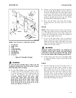
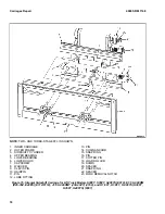
Connect a crane [the capacity of the crane must
be at least 681 kg (1501 lb)] to the lifting eye on
the sideshift carriage. See Figure 12.
3.
Remove the two upper capscrews from the
lower apron. Slowly loosen the two bottom cap-
screws, but do not remove them. The slotted
holes will allow the lower apron to move down
so the sideshift carriage can be removed.
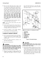
4.
Carefully lift the sideshift carriage from the
standard carriage. The sideshift cylinder sup-
port bracket and cylinder will stay on the
standard carriage. Remove the bearings.
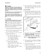
WARNING
Always wear the proper protective equipment in-
cluding eye protection and petroleum-resistant
gloves when handling hydraulic oil. Thoroughly
wash oil from exposed areas of skin as soon as
possible.
The hydraulic oil is hot at normal operating tem-
peratures. Be careful when draining the oil.
Never check for leaks by putting hands on hy-
draulic lines or components under pressure. Hy-
draulic oil under pressure can be injected into the
skin.
CAUTION
Protect the hydraulic system from dirt and con-
taminants when servicing the hydraulic system.
5.
Disconnect the hydraulic lines at the sideshift
cylinder. Put caps on the open hydraulic lines.
Remove the cylinder support bracket from the
standard carriage. If necessary, remove the
threaded rods and shims in order to remove the
sideshift cylinder.
STANDARD CARRIAGE AND HANG-ON
SIDESHIFT CARRIAGE, REPAIR
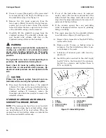
NOTE:
The carriage can have four or six load roll-
ers. When the carriage has four load rollers, shims
are used behind all of the load rollers. When the
carriage has six load rollers, shims are installed on
the bottom and middle rollers only.
1.
If any of the load rollers must be replaced,
make a note of the location and number of the
shims. Install the shims, load rollers, and snap
rings. See Carriage Adjustments for correct ad-
justment of the load rollers.
2.
If the carriage aprons have any protruding
welds or damaged notches, repair by grinding,
filing, or welding.
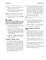
3.
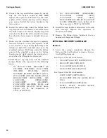
The repair procedure for the sideshift cylinder
is as follows (see Figure 12 and Figure 13):
a.
Remove the retainers from the shell. Pull the
rod from the shell.
b.
Replace seals, O-rings, or backup rings as
necessary. Use the installation guides to pre-
vent damage to the seals.
c.
Lubricate all internal parts with clean hy-
draulic oil.
d.
Install the piston and rod in the shell. Apply
Loctite
®
242 to the threads of the retainers.
Install the retainers and tighten them to
27 N•m (20 lbf ft).
1. SHELL
2. O-RING
3. BACKUP RING
4. ROD SEAL
5. RETAINER
6. WIPER
7. PISTON AND ROD
8. PISTON SEAL
Figure 13. Sideshift Cylinder
Carriages Repair
4000 SRM 1148
14


