CAUTION
Remove fork latch pins if adding a fork positioner
attachment. Damage to forks and other carriage
components can occur if fork latch pins are not
removed prior to using attachment.
NOTE:
Forks are to be replaced in sets, not indi-
vidually, by trained personnel only.
1.
Move carriage into position to install forks.
2.
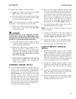
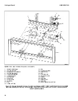
Use lifting device and slide forks onto fork car-
riers. See Figure 7.
NOTE:
Install fork carrier blocks and retainer cap-
screws in hole positions on fork carriers as noted
during removal.
3.
Install fork carrier blocks and retainer cap-
screws in hole positions on fork carriers as no-
ted during removal.
4.
Tighten
retainer
capscrews
to
100 N•m (75 lbf ft).
NOTE:
DIMENSIONS SHOWN ON BOTTOM OF FORK CARRIERS ARE THE WIDTH OF THE FORK BEING
INSTALLED. THE TWO STAGE LFL CARRIAGE AND THE THREE STAGE FFL CARRIAGE ARE THE SAME.
1. RETAINER CAPSCREW
2. FORK CARRIER
3. FORK CARRIER BLOCK
Figure 7. Hole Location, Fork Mounting on Fork Carriers
CHECKS, LIFT TRUCKS NOT EQUIPPED
WITH FORK POSITIONER OR EQUIPPED
WITH FORK POSITIONER BEFORE
AUGUST, 2012
WARNING
Never repair damaged forks by heating or weld-
ing. Forks are made of tempered steel using spe-
cial procedures. Always replace damaged forks as
a pair.
1.
Inspect forks for cracks and wear.
2.
Check alignment of fork tips. Difference in
height of fork tips must be less than three per-
cent of fork length. See Table 1 and Figure 8.
Some applications may require closer align-
ment. If forks DO NOT meet specification they
both must be replaced.
Fork Replacement
4000 SRM 1148
8


