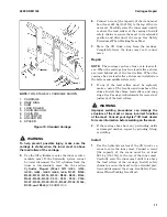
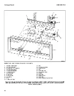
Hyster J160 Manual Download Page 17

NOTE: 

TWO-STAGE LFL CARRIAGE SHOWN.

1. CARRIAGE

2. SNAP RING

3. SHIM

4. LOAD ROLLER

5. CHAIN ANCHOR

6. CHAIN PIN

7. COTTER PIN

8. ANCHOR PIN

9. SPACER

Figure 10. Standard Carriage

  WARNING 

To  help  prevent  possible  injury,  make  sure  the
carriage  is  stable  when  the  inner  mast  is  above
the load rollers of the carriage.

5. 

Use the lift cylinders to raise the inner or inter-
mediate  mast.  If  the  hydraulic  system  cannot
be  used,  disconnect  the  lift  cylinders  from  the
inner  or  intermediate  mast.  See  the  section
Cylinder  Repair  (Mast  S/N  A551,  A555,
A559,  A661,  A662,  A663,  A66,  B507,  B508,
B509,  B551,  B555,  B559,  B562,  B563,  B564,
B661,  B662,  B663,  C515,  C551,  C555,  C559,
D507, D508, D509, D515, D562, D563, D564,
E509, and E564)
 2100SRM1139.
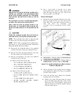
6. 

Connect a crane [the capacity of the crane must
be at least 681 kg (1501 lb)] to the top of the in-
ner mast. Carefully raise the inner mast until it
is above the load rollers of the carriage. Install
safety chains to secure the mast in its extended
position  and  disconnect  the  crane.  See  Safety
Procedures When Working Near Mast
.

7. 

Move  the  lift  truck  away  from  the  carriage.
Completely  lower  the  inner  mast  so  it  cannot
move.

Repair

NOTE:  

The carriage can have four or six load roll-

ers. When the carriage has four load rollers, shims
are  used  behind  all  of  the  load  rollers.  When  the
carriage has six load rollers, shims are installed on
the bottom and middle rollers only.

1. 

If  any  of  the  load  rollers  must  be  replaced,
make a note of the location and number of the

shims. Install the shims, load rollers, and snap
rings. See Carriage Adjustments for correct ad-
justment of the load rollers.

  WARNING 

Improper  welding  procedures  can  damage  the
structure  of  the  mast  or  cause  incorrect  function
of the mast. Consult your Hyster

®

 lift truck dealer

for more information before welding on the mast.

2. 

If the carriage bars have any protruding welds
or  damaged  notches,  repair  by  grinding,  filing,
or welding.

Install

1. 

Use  the  hydraulic  system  of  the  lift  truck  or  a
crane to raise the inner mast. Connect a crane
[the  capacity  of  the  crane  must  be  at  least
681  kg  (1501  lb)]  to  the  top  of  the  inner  mast.
Carefully raise the inner mast until it is above

the  load  rollers  of  the  carriage.  Install  safety
chains to secure the mast in its extended posi-
tion and disconnect the crane. See Safety Proce-
dures When Working Near Mast.

4000 SRM 1148

Carriages Repair

11

Summary of Contents for J160

Page 1: ...Hyster J160 J30ZT J35ZT J40ZT Forklift...

Page 2: ...508 D509 D515 D562 D563 D564 E509 AND E564 2 3 AND 4 STAGE MASTS S30FT S35FT S40FTS E010 H1 6FT H1 8FT H2 0FTS H30FT H35FT H40FTS F001 S2 0 3 5FT S40 70FT S55FTS F187 H2 0 3 5FT H40 70FT L177 E1 50 2...

Page 3: ...dic Maintenance section Keep the unit clean and the working area clean and orderly Use the correct tools for the job Keep the tools clean and in good condition Always use HYSTER APPROVED parts when ma...

Page 4: ...ge 10 Remove 10 Repair 11 Install 11 Standard Carriage Remove 12 Hang On Sideshift Carriage Remove 13 Standard Carriage and Hang On Sideshift Carriage Repair 14 Standard Carriage Install 15 Hang On Si...

Page 5: ...ore information Please click here Then get the complete manual NOTE If there is no response to click on the link above please download the PDF document first and then click on it Have any questions pl...

Page 6: ...ur Stage FFL Mast Manufactured After July 2009 126 Adjustment 133 Lift Chains Adjustment 133 Carriage Adjustments 136 Mast Adjustments 136 Load Roller Adjustment 136 Mast Side Kicking Adjustment 139 T...

Page 7: ...djustments are located at the end of this section NOTE For models J1 60 2 00XMT J30 40ZT J160 this section applies to only to Four Stage masts Refer to Mast Repairs 4000SRM0522 for Two Stage and Three...

Page 8: ...at move are fully lowered OR If parts of the mast must be in a raised posi tion install a safety chain to restrain the moving parts of the mast Connect moving parts to a part that does not move Follow...

Page 9: ...GE FFL MAST D FOUR STAGE FFL MAST 1 OUTER MAST 2 INNER MAST 3 INTERMEDIATE MAST 4 HOOK 5 FREE LIFT CYLINDER 6 CARRIAGE BAR 7 CROSSMEMBER 8 FIRST INTERMEDIATE MAST Figure 1 Safety Chaining the Mast 400...

Page 10: ...place damaged fork pin parts Forks are removed from carriage by aligning forks with fork removal notch Fork removal notch is in bottom bar of carriage See Figure 4 Forks used on an integral sideshift...

Page 11: ...rk moves through fork removal notch See Fig ure 4Figure 5 3 Lower carriage further so top hook of fork is disengaged from top carriage bar 4 Move carriage away from fork or use a lifting device to mov...

Page 12: ...chment Damage to forks and other carriage components can occur if fork latch pins are not removed prior to using attachment NOTE Forks are to be replaced in sets not indi vidually by trained personnel...

Page 13: ...ch hook fork for these lift trucks can weigh 45 to 115 kg 99 to 254 lb 1 Move fork and carriage so top hook of fork can engage upper carriage bar 2 Raise carriage to move bottom hook of fork through f...

Page 14: ...lbf ft NOTE DIMENSIONS SHOWN ON BOTTOM OF FORK CARRIERS ARE THE WIDTH OF THE FORK BEING INSTALLED THE TWO STAGE LFL CARRIAGE AND THE THREE STAGE FFL CARRIAGE ARE THE SAME 1 RETAINER CAPSCREW 2 FORK CA...

Page 15: ...s and lu bricate as necessary See Figure 4 CHECKS LIFT TRUCKS MANUFACTURED AFTER AUGUST 2012 AND EQUIPPED WITH FORK POSITIONER WARNING Never repair damaged forks by heating or weld ing Forks are made...

Page 16: ...lifting device to the carriage Lift the carriage so that the lift chains become loose WARNING When disconnecting the lift chains keep control of the ends Use wire to temporarily connect the ends of t...

Page 17: ...e Completely lower the inner mast so it cannot move Repair NOTE The carriage can have four or six load roll ers When the carriage has four load rollers shims are used behind all of the load rollers Wh...

Page 18: ...bility so the carriage cannot fall when it is disconnected from the mast 2 Lower the carriage and forks on blocks so the lift chains become loose 3 Remove the load backrest WARNING When disconnecting...

Page 19: ...the floor so the load rollers are up HANG ON SIDESHIFT CARRIAGE REMOVE 1 Lower the carriage completely Remove the forks and the load backrest extension A HYDRAULIC CONNECTIONS TWO STAGE FULL FREE LIF...

Page 20: ...der support bracket from the standard carriage If necessary remove the threaded rods and shims in order to remove the sideshift cylinder STANDARD CARRIAGE AND HANG ON SIDESHIFT CARRIAGE REPAIR NOTE Th...

Page 21: ...o secure the mast in its extended posi tion and disconnect the crane See Safety Proce dures When Working Near Mast 2 Move the lift truck toward the carriage until the inner mast is aligned with the ca...

Page 22: ...25 35XM H S40XMS E1 50 1 75XM E25 35XM E25 35XM2 D114 E2 00XMS E40XMS E40XM2S D114 E1 50 2 00XM E25 35Z E40ZS E114 H S2 00 2 75XM H S40 55XM S E J2 00 2 50XL S E J40 50XL J1 60 2 00XMT J30 40XMT J2 00...

Page 23: ...AIRPIN 11 PIN 12 LUBE FITTING 13 PIN 14 CHAIN ANCHOR 15 SNAP RING 16 PIN 17 COTTER PIN 18 LOAD ROLLER 19 SHIMS 20 SPACER 21 SNAP RING 22 SPACER 23 FORK REMOVAL NOTCH Figure 14 Integral Sideshift Carri...

Page 24: ...12 LUBE FITTING 13 PIN 14 CHAIN ANCHOR 15 SNAP RING 16 PIN 17 COTTER PIN 18 LOAD ROLLER 19 SHIMS 20 SPACER 21 SNAP RING 22 SPACER 23 FORK REMOVAL NOTCH Figure 15 Integral Sideshift Carriage for Lift...

Page 25: ...T S55FTS F187 H2 0 3 5FT H40 70FT L177 J2 00 3 20XM J40 65Z B416 E2 00 3 20XM E45 65Z G108 See Figure 15 for lift truck models S30FT S35FT S40FTS E010 E1 50 2 00XM E25 35Z E40ZS E114 F114 J1 60 2 00XM...

Reviews: