User manual R3
DLCP
- 7 -
2.3
Recommended Operating Conditions
Item
Symbol
Min
Typ
Max
Unit
Notes
Supply voltage
15.5
1)
18
26
2)
Vdc
Positive and negative sup-
ply voltage
Note 1:
Unit shuts down when the positive rail drops below 15V.
Note 2:
Especially on high supply voltages; make sure there’s enough airflow to cool the regulators.
2.4
Hardware Architecture
2.4.1
Analogue input
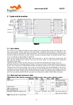
The DLCP has two (stereo) analogue balanced audio inputs. The analogue input signal is buffered
and amplified by a single-stage, fully differential programmable gain amplifier and then converted to
digital by the ADC. The ADC is always directly clocked by the on-board oscillator, a low noise Colpitts
oscillator with a locally regulated supply, causing less jitter. After the analogue to digital conversion
the signal is processed by the DSP.
2.4.2
Digital input
The DLCP contains four separate digital inputs, permitting the use of different interconnection
standards (AES/EBU and S/PDIF). Optimal clock quality is insured by routing the clock through sepa-
rate IC’s from the data signals, and by local regulation of all supplies on the AES input circuit.
Incoming AES / S/PDIF is send to the DSP through an asynchronous sample rate converter (ASRC) to
reduce jitter.
When the input is set to “Auto detect”, the ASRC chip scans its inputs for whichever digital signal is
present. The input source is automatically switched to digital when present, using the priority de-
scribed below. If the digital audio source is removed, the input will be automatically switched back
the last chosen analogue input.
Auto detect input priority high to low:
1)
AES
2)
SPDIF
3)
USB_audio
4)
Optical
2.4.3
Digital output
The DLCP contains two separate digital outputs, AES/EBU and S/PDIF. The selected digital input is
directly send to both digital outputs. (Without filtering)
2.4.4
DSP
The DSP filtering can be changed by Hypex Filter Design (HFD) software. The digital outputs from the
DSP are fed to the DACs. The DAC chip receives data from the DSP and clock either from the crystal
oscillator or from the digital input section. The digital signal is then converted to analogue by the
DAC. The post filter is executed twice, providing a balanced load to the DAC and delivering a high
output level to the power amplifier.
2.4.5
Microcontroller
A microcontroller controls the DSP and other ICs and I/O’s on the PCB, communicates with the con-
trol board, PC and/or other DLCP’s that may be attached. When the module is powered on it will au-
tomatically start up with the last settings. All settings, like volume and source selection, are stored
after a change is made.


