User manual R3
DLCP
- 10 -
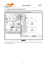
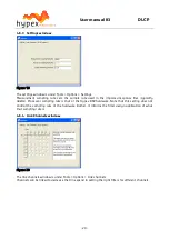
2.5.1.3
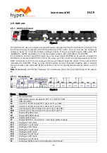
Settings
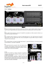
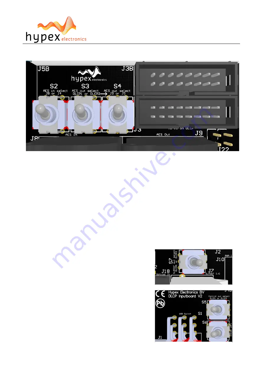
Figure 6
S2:
S2 selects the AES input for the DLCP connected to J2/J3, set in the position shown in Figure 6 in
order to use the digital XLR input, and other position to use the AES input from the control cable.
S3:
Set the switch in the position in Figure 6 if one DLCP is connected, and other position if there is an-
other DLCP connected to J2B/J3B.
S4:
Set in position shown in Figure 6 to use J9 as digital XLR output or in the other position to send the
digital signal thru the control cable, this can save cabling when using the AES as input in combina-
tion with more input boards.
S1:
Set in down position to connect the USB cable to DLCP 1 (connected to J2/J3), set in the up position
to control DLCP 2 (connected to J2B/J3B).
S7:
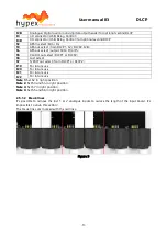
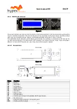
This switch selects the source for the cinch digital output
(J7 white). Set the switch in the position shown in Figure 7
if one DLCP is connected, set in the other position if there is
another DLCP connected to J2B/J3B.
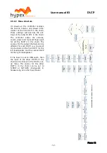
S5, S6:
Set S5 in the position as shown in Figure 8 if one DLCP is
connected, set in the other position if there is another DLCP
connected to J2B/J3B.
Set S6 in the position as shown in Figure 8 if this input
board contains the last DLCP in the chain. In this way the
last DLCP sends it control output back to the DLCP control,
to make a loop. Set S6 in the other position if there is an-
other DLCP connected to J5B/J5B.
Figure 7
Figure 8


