User manual R3
DLCP
- 13 -
3
Product overview
Before you can use the DLCP in your particular setup you first have to set the right settings (hard-
ware and software). This chapter describes the hardware part, where chapter 4 describes the soft-
ware part.
3.1
DLCP setups
The DLCP can be used in many ways, therefore it’s not possible to describe all options. (Please e-mail
to
if you have questions about your particular setup.)
3.1.1
Example 1: DLCP as preamplifier
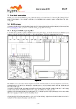
In combination with the optional DLCP input board with relays, and control board, the DLCP can be
used as a high-end active pre amplifier. This example doesn’t use the dedicated SMPS DLCP.
Figure 13
The DLCP can be connected to the input board with two flat cables. J2 on the input board must be
connected to J2 on the DLCP (Analogue / Digital Input). J3 on the input board must be connected to
J3 on the DLCP (I/O).
The DLCP Control can be connected to J4B on the input board (to keep the wire internal). The supply
can be connected to the DLCP with J16 or J4, only V+/GND/V- must be present.
Optional the standby voltage can be applied to J17, please use the supply standby pin to shut down
the main supply in order to use the standby mode.
The amplifiers can be connected to J1 or J10-J15 (preferably). Optional an external LED can be con-
nected to J7 to indicate the power on/off state.


