User manual R3
DLCP
- 11 -
2.5.2
DLCP Control board
Figure 9
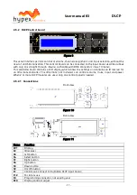
The serial interface permits control of volume, channel assignment, and input selection, without the
need of an USB connection. This control board can be connected to the input board described above
with only one straight through (8-wire) cat5 cable with RJ45 connectors (max. 10 meter).
This controller board contains a LCD display which shows the settings and contains an IR receiver for
an IR remote controller. The IR remote (not included) can control volume, mute, input and power.
When 2 or more DLCP modules are used, only one control panel is needed.
2.5.2.1
Connections
Front view
Figure 10
Back view
Figure 11
Name
Function
JP1
Display
J2
IR receiver
S6
Left button
S4
Select button
S1
Right button
S5
Up button
S3
Down button
S2
On/Off button
J1
Control out (connect to J4/J4B on DLCP input board)
J12
For future use
J3
Programming connector, not used by user
R10
Display contrast adjust


