User manual R3
DLCP
- 23 -
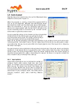
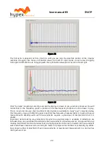
The steps of loading and truncating data can be repeated at any time. This can be particularly prac-
tical when combining close-up and far-field measurements during the filter design phase. The win-
dow in Figure 23 shows the result of this. The small knot of corrections made around 70Hz is based
on close-up data first loaded separately. The LF section of the test mule is quite smooth apart from
one internal standing wave.
4.6.7
Designing filters
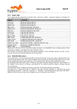
Biquad function
Parameters
Use
Unity
-
Section is not used
LPF1
Cut-off frequency (always -3dB)
First order low pass
LPF2
Cut-off frequency (asymptotically)
Q
Second order low pass. A Q of 0.71 cor-
responds to Butterworth. 0.5 corre-
sponds to LR2. Two identical sections
with a Q of 0.71 form an LR4 filter.
HPF1
Cut-off frequency (always -3dB)
First order high pass
HPF2
Cut-off frequency (asymptotically)
Q
Second order high pass. A Q of 0.71 cor-
responds to Butterworth. 0.5 corre-
sponds to LR2. Two identical sections
with a Q of 0.71 form an LR4 filter.
Shelf1
Centre Frequency (halfway point)
Gain
Direction
First order shelf. Useful for baffle-step
correction
Shelf2
Centre Frequency (halfway point)
Gain
Q
Direction
Second order shelf. Useful for correcting
internal cabinet resonances and for the
midband peak/dip combo of most mid-
woofer speakers.
Asymmetric Shelf Pole frequency and Q
Zero frequency and Q
Equalizing the bottom end of closed-box
woofers with large magnets
Boost/Cut
Centre frequency
Q
gain
Dip/peak filter. For peaks, Q is defined
by the poles. For dips, Q is defined by
the zeros. Thus the same filter with op-
posite gains will cancel.
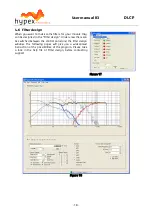
The first step is equalizing the magnitude responses of the drivers flat over their entire useable fre-
quency range.
The weapons of choice are shelving filters, and boost/cut sections. A sharp peak followed by an
equally sharp dip can be corrected using a second-order shelving filter with a high Q.
Exercise care when deciding what to correct. When correcting for diffraction errors, do not exceed a Q
of 3 lest the cure be worse than the ailment. Errors that are caused inside the driver, or internal cabi-
net resonances that emanate through the same diaphragm, may be corrected ruthlessly – provided
the measurement has sufficient resolution to pin them down.
As a rule of thumb, sharp dips are diffraction artefacts while sharp peaks are caused by the drivers
themselves. Exceptions are room resonances (if the response is not correctly truncated) and diffrac-
tions on repetitive patterns.
The second step is designing the actual crossover filters. All the usual strategies work. Delaying
higher frequency drivers with respect to lower-frequency ones is a powerful alternative to using
asymmetric slopes and yields substantially improved coherence through the crossover region.
4.6.8
Download
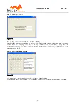
Under download the user can press “load DSP” to download the designed filters into the module.
4.6.9
Save files
Under filter design there is an option to save all filter settings together with the measurements so it
can be reloaded afterwards. Till now it is not possible to read back the filters out of the modules. Alt-

