2
11
502 50 18-01
502 51 49-01
E
E
E
F
G
Electrical system
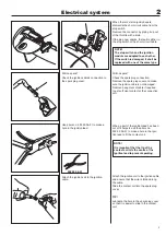
Dismantle the short-circuit cable from the
ignition module.
Dismantle the short-circuit cable from the
ignition module by removing the screw (F)
and prying off the
fl
at pin connector (G).
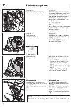
Dismantle the guard plate under the en-
gine body (2 remaining screws).
Lift out the ignition lead and short-circuit
cables from their guides.
Remove the 3 screws (E) and swing the
engine body to one side so the clutch
becomes accessible.
Remove the nut holding the
fl
ywheel.
Remove the nut holding the
fl
ywheel.
Fit the puller on the
fl
ywheel. Loosen and
remove the nut.
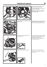
Dismantle the ignition module and the
centrifugal clutch.
Remove the remaining screws (A) holding
the ignition module and both screws (B)
that hold the centrifugal clutch.
Lift off the clutch, both support washers
and the ignition module.
Summary of Contents for 241R
Page 1: ...Workshop manual 241R 241RJ English ...
Page 35: ...4 34 Centrifugal clutch ...
Page 49: ...6 48 Cylinder and piston ...
Page 59: ...58 8 List of tools ...
Page 62: ...2008W37 115 11 96 26 ...


