7
53
1
2
3
4
502 50 18-01
502 50 70-01
Crankshaft and crankcase
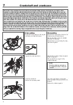
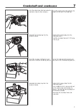
Fit the sealing rings in the crankcase
halves.
Fit the crankshaft, guide sleeves and
guide rail in the clutch side’s crankcase
half.
Place a new crankcase gasket in position.
Fit the
fl
ywheel side’s crankcase half.
Tighten the 4 crankcase screws cross-
wise.
Assemble the piston.
Attach the
fl
ywheel.
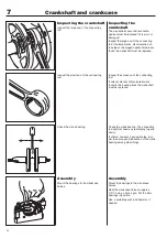
Fit the sealing rings in the crankcase
halves with the help of a suitable punch.
Turn the sealing rings so the metal collar
faces outwards.
Fit the crankshaft in the clutch side’s
crankcase half. Lubricate the stub axle
with a few drops of oil and carefully slide
in the crankshaft in the ball-bearing so
that the sealing ring is not damaged by
the shoulder on the stub axle.
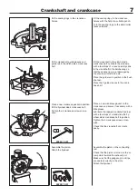
Place the guide rail in position in the
fl
ush
channel.
Place the 2 guide sleeves in the crank-
case half.
Place a new crankcase gasket on the
crankcase and secure if necessary with a
little grease.
Lubricate the tapered crankshaft journal
with a few drops of oil and slide the
fl
y-
wheel side’s crankcase half in position.
Tighten the 4 crankcase screws cross-
wise.
Check that the crankshaft can rotate
easily.
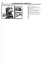
Assemble the piston on the connecting
rod.
Check that the piston is turned so the ar-
row points towards the exhaust port.
Make sure that the gudgeon pin circlips
are seated correctly in the slots.
Attach the
fl
ywheel.
Summary of Contents for 241R
Page 1: ...Workshop manual 241R 241RJ English ...
Page 35: ...4 34 Centrifugal clutch ...
Page 49: ...6 48 Cylinder and piston ...
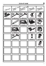
Page 59: ...58 8 List of tools ...
Page 62: ...2008W37 115 11 96 26 ...

