4
30
Centrifugal clutch
The centrifugal clutch has the task of transferring the power from the engine to the cutting
equipment’s drive axle. As the name implies, it works according to a centrifugal principle.
This means the clutch’s friction shoes are thrown outwards towards the clutch drum at a certain
engine speed. When the friction against the drum is suffi ciently great it drives the drive shaft at
the same speed as the engine.
Some slipping occurs between the clutch and the clutch drum when accelerating as well as in the
reversed situation when the cutting equipment jams. Thereby preventing abnormal load changes
on the crankshaft.
The engagement speed has been carefully tested so that the engine can idle without the cutting
equipment’s drive shaft rotating.
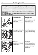
Dismantling opt.
B
Dismantle the protective plate under the
engine body (3 screws), the cylinder cover
and the throttle cable on the carburettor.
Lift out the ignition lead and short-circuit
cables from their guides.
Remove the 3 screws (E) and swing the
engine body to one side so the clutch
becomes accessible.
Dismantle the protective plate, the
cylinder cover and throttle cable on the
carburettor. Remove the 3 screws (E) and
swing the engine body to one side.
Dismantle the protective plate under the
engine body (3 screws), the cylinder cover
and the throttle cable on the carburettor.
Remove the 3 screws (E) and swing the
engine body to one side so the centrifugal
clutch becomes accessible.
Dismantling opt.
B
Dismantle the protective plate, the cylinder
cover and throttle cable on the carburettor.
Remove the 3 screws (E) and swing the
engine body to one side.
Centrifugal clutch
Dismantling opt. A
Remove the cover over the air
fi
lter, cylin-
der cover and the cover over the muf
fl
er.
Loosen the screw and slide the cable
holder (B) forwards.
Remove the screws and slide the cover
(D) forwards.
Centrifugal clutch
Dismantling opt. A
Remove the cover over the air
fi
lter, cylin-
der cover and the cover over the muf
fl
er.
Loosen the screw (A) and slide the cable
holder (B) forwards on the shaft.
Remove the screws (C) and slide the
cover (D) forwards on the shaft.
Summary of Contents for 241R
Page 1: ...Workshop manual 241R 241RJ English ...
Page 35: ...4 34 Centrifugal clutch ...
Page 49: ...6 48 Cylinder and piston ...
Page 59: ...58 8 List of tools ...
Page 62: ...2008W37 115 11 96 26 ...

