background image

POWERVIEW

®

 DECLARATIONS

31

U.S. Radio Frequency FCC Compliance

FCC ID information is located behind the motor-side end cap. The end cap may be removed to view this 

information.

This device complies with Part 15 of the FCC Rules. Operation is subject to the following two conditions:  

(1) This device may not cause harmful interference, and  

(2) This device must accept any interference received, including interference that may cause undesired operation.
This equipment has been tested and found to comply with the limits for a Class B digital device, pursuant to Part 

15 of the FCC Rules. These limits are designed to provide reasonable protection against harmful interference in a 

residential installation. This equipment generates, uses and can radiate radio frequency energy and, if not installed 

and used in accordance with the instructions, may cause harmful interference to radio communications. However, 

there is no guarantee that interference will not occur in a particular installation. If this equipment does cause 

harmful interference to radio or television reception, which can be determined by turning the equipment off and 

on, the user is encouraged to try to correct the interference by one or more of the following measures:

• Reorient or relocate the receiving antenna.

• Increase the separation between the equipment and receiver.

• Connect the equipment into an outlet on a circuit different from that to which the receiver is connected.

• Consult the dealer or an experienced radio/TV technician for help.

Any changes or modifications not expressly approved by the party responsible for compliance could void the user’s 

authority to operate the equipment.

This equipment complies with FCC radiation exposure limits set forth for an uncontrolled environment and meets 

the FCC radio frequency (RF) Exposure Guidelines. This equipment should be installed and operated keeping the 

radiator at least 20 cm or more away from person’s body. RF Exposure requirements are met when installed in 

mobile equipment. This module cannot be installed in portable equipment without further testing and a change to 

FCC’s grant of authorization.

Industry Canada

Under Industry Canada regulations, this radio transmitter may only operate using an antenna of a type and 

maximum (or lesser) gain approved for the transmitter by Industry Canada. To reduce potential radio interference 

to other users, the antenna type and its gain should be so chosen that the equivalent isotropically radiated power 

(e.i.r.p.) is not more than that necessary for successful communication.
This device complies with Industry Canada licence-exempt RSS standard(s). Operation is subject to the following 

two conditions: (1) this device may not cause interference, and (2) this device must accept any interference, 

including interference that may cause undesired operation of the device.

Class B Digital Device Notice

This Class B digital apparatus complies with Canadian ICES-003, RSS-Gen and RSS-210. 
CAN ICES-3 (B)/NMB-3(B)
This equipment complies with IC radiation exposure limits set forth for an uncontrolled environment and meets 

RSS-102 of the IC radio frequency (RF) Exposure rules. This equipment should be installed and operated keeping 

the radiator at least 20 cm or more away from person’s body.

European Conformity

We, the undersigned,
Hunter Douglas Window Fashions 

One Duette Way, Broomfield, CO 80020, USA
Hunter Douglas Europe B.V. 

Piekstraat 2, 3071 EL Rotterdam, The Netherlands
certify and declare under our sole responsibility that assembly PV9 conforms with the essential requirements of 

the EMC directive 2004/108/EC and R&TTE directive 1999/5/EC.
A copy of the original declaration of conformity may be found at:  

www.hunterdouglas.com/RFcertifications

.

Summary of Contents for Silhouette Duolite Window Shadings PowerView Motorization

Page 1: ...UltraGlide PowerView Motorization SoftTouch Silhouette Duolite Window Shadings UltraGlide SoftTouch and PowerView Motorization Operating Systems Installation Operation Care...

Page 2: ...Installation Brackets Outside Mount 6 STEP 2 PowerView and SoftTouch Only Connect the Power Cable 8 STEP 3 Install the Shading 9 Install the Optional Back Cover If Applicable 9 Mount the Headrail 9 A...

Page 3: ...ck Cover For Inside Mount Installation Brackets Limit Stops Tassel Cord UltraGlide Headrail Roller Shade Bottom Rail Rear Roller Shade Front Shading Shading Bottom Rail Tassel Programming Button Batte...

Page 4: ...hment Speed Nuts and Screws Provided Extension brackets come with screws and speed nuts Drywall Anchors Not Provided Use drywall anchors when mounting into drywall 6 x 11 2 Hex Head Screw Provided Spe...

Page 5: ...ting Types and Window Terminology If the installation brackets are mounted correctly the rest of the installation process follows easily To prepare for this important first step review the mounting ty...

Page 6: ...e a battery wand remove the bottom tab from the back cover bracket Snap the back cover bracket into the metal installation bracket This ensures adequate space for the battery wand If you have a satell...

Page 7: ...32 drill bit to drill holes for the mounting screws CAUTION Use drywall anchors when mounting into drywall Attach the installation brackets using the screws provided NOTE Do not overtighten the screws...

Page 8: ...d mark the location of the screw holes A minimum 1 flat vertical height is required to mount the installation brackets Position the top of the installation brackets at the desired height of the shadin...

Page 9: ...face Additional Clearance with Extension Brackets If using extension brackets attach each extension bracket to the mounting surface using the screws provided Attach an installation bracket to the unde...

Page 10: ...ttery wand with its socket toward the motor end of the shading Push the battery wand straight up into the battery wand clips until it snaps into place Check to make sure the battery wand is secure CAU...

Page 11: ...ing from the top of the Palette fabric covered headrail Leave the rest of the protective covering on the front of the headrail Position the shading so that the front faces you Slide the headrail into...

Page 12: ...ed width Remove the paper backing on one side of the hook and loop fastener dots Apply the dots to the installation brackets on each end of the shading Remove the remaining paper backing from the dots...

Page 13: ...Decide where you want to attach the wall mount bracket for the satellite battery pack It may be installed in any orientation Mark the screw holes and drill them using a 3 32 drill bit Remove the backi...

Page 14: ...e the operation of the shading Space the wire retainers approximately 15 apart along the extension cable as shown at far right WARNING Keep cords and small parts out of the reach of children They can...

Page 15: ...age 14 For the PowerView Motorization system see page 16 Shown below are a few examples of possible front shading and rear shade positions UltraGlide When the cord is pulled toward the center of the s...

Page 16: ...to the fully raised position 2 Push up and release The vanes close 3 Push up and release The front shading moves to the fully raised position To Close the Shading Pull the wand down and release to seq...

Page 17: ...position is the rear shade fully raised and the front shading at 50 open with the vanes closed Set a Favorite With the rear shade fully raised and the front shading vanes closed Put the shading in mo...

Page 18: ...n raising the rear shade and front shading for the first time observe how the fabric rolls up into the headrail It should roll up evenly If the bottom rail is not level or the fabric starts to rub aga...

Page 19: ...g s to move Selected group button s will light to show they are selected Multiple group buttons may be selected at a time To deselect a group press the group button again The backlight for that group...

Page 20: ...t mode NOTE If the shading moves or the programming button flashes green repeat steps 1 and 2 3 Use OPEN n STOP and CLOSE on the remote to lower the shading or raise the shading as far as possible wit...

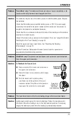
Page 21: ...c Reset The basic reset is used to reset the shading s travel limits 1 Press and hold the programming button for approximately 6 seconds The shading will move slightly Release the programming button t...

Page 22: ...ted into the installation brackets so that the locking lever on the installation bracket slides over the headrail See STEP 3 Install the Shading on page 9 If a PowerView shading has a battery wand che...

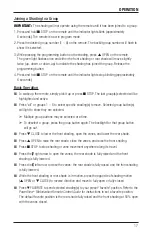
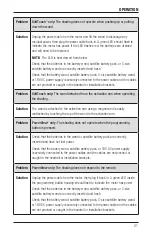
Page 23: ...ivation arm using a magnet and is easily reattached by touching the top of the wand to the activation arm Problem PowerView only The shading does not operate when the programming button is pressed Sol...

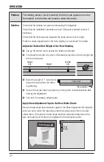
Page 24: ...tom rail weight To release the weight clip insert a flat blade screwdriver into the weight clip and turn clockwise Move the weight in 1 increments toward the side where the fabric is gathering Secure...

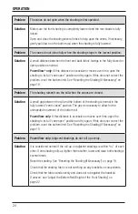
Page 25: ...ment The limit stop catches the bottom rail and the bottom of the limit stop is slightly above or barely touching the fabric roll In the second illustration the limit stop adjustment is too tight The...

Page 26: ...n the vanes are closed Solution A small gap between the sill and the bottom of the shading is normal in the fully lowered vane closed position The gap is necessary to allow for the unimpeded movement...

Page 27: ...9 See the PowerView Motorization Remote Control Guide for operation or programming troubleshooting solutions Problem UltraGlide only The tassel cord and lower cord connector have detached from the upp...

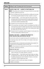
Page 28: ...p The red LED turns off Release the wand The shading movement indicates the new upper limit is set and the shading exits programming mode Adjust the Lower Limit available for Rear Shade only Vanes Clo...

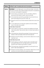
Page 29: ...oves to the vanes closed position Set the Vanes Closed Limit Push the wand up or pull down to move the front shading to the desired closed vanes position Stop movement when the desired closed position...

Page 30: ...bracket Carefully pull the headrail to completely remove the shading from the brackets Cleaning Procedures Silhouette Window Shadings are made of 100 polyester which means they are inherently durable...

Page 31: ...Cleaning the Rear Roller Shade The rear roller shade fabric can be cleaned by dusting hand held vacuuming compressed air hair dryer on the cool setting and the dry method of injection extraction A Not...

Page 32: ...ys keep cords out of the reach of children Move cribs playpens and other furniture away from cords Children can climb furniture to get to cords NOTE The warning labels on the bottom rails of corded wi...

Page 33: ...nt and meets the FCC radio frequency RF Exposure Guidelines This equipment should be installed and operated keeping the radiator at least 20 cm or more away from person s body RF Exposure requirements...

Page 34: ...Notes...

Page 35: ......

Page 36: ...ED WARRANTY Hunter Douglas window fashion products are covered for defects in materials workmanship or failure to operate for as long as the original retail purchaser owns the product unless shorter p...

Reviews: