background image


Built on Innovation

®


15

Basic Programming and Setup

MANUAL STARTS AND TEST

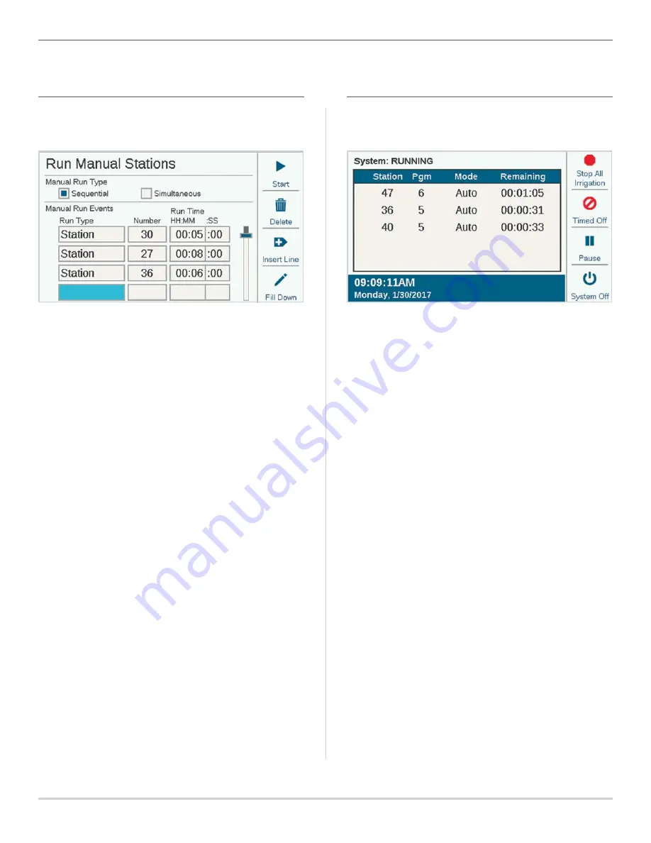
On the Home screen, the Manual soft key lets you start 
stations, programs, or a Test program. Once you press 
Manual, there are three choices:

MANUAL STATIONS

Specify one or more stations to run and enter a run time for 
them. You can also choose to run them simultaneously, rather 
than sequentially, if you check the Simultaneous box. Press 
the Start key to start the list.

MANUAL PROGRAM

Select a program number to start, and press the Start key 
to start it. It is also possible to scroll down to an event in the 
program, and start the program from that point forward.

A Manual Station or Program Start will pause any automatic 
watering until the Manual Program has completed.

TEST PROGRAM

The Test program will run all stations in the controller for the 
Run Time entered on the screen. It is also possible to specify 
a station number, and run all remaining stations from that 
number to the highest numbered station.

In the ACC2 Decoder controller, the Test Program will only run 
stations that already have a run time in other programs in the 
controller.

STOP COMMANDS

Any running irrigation can be stopped immediately from the 
Home screen. The top soft key offers the following choices for 
stopping irrigation: 

STOP ALL IRRIGATION

This immediately stops everything that is watering or running. 
The controller is still in Automatic irrigation mode, and will 
resume watering at the next start time.

TIMED OFF

Like System Off, this stops all stations and prevents automatic 
irrigation, but for a specified period of days. When the 
days have counted down to zero, the controller will resume 
automatic operations.

PAUSE

This interrupts whatever is currently running, until either 
Resume is pressed or 30 minutes have passed. Anything 
running will be resumed where it left off, and run for its 
remaining time. When items are paused, the Resume button 
will appear.

SYSTEM OFF

This turns off all irrigation, and places the controller in 
permanent Off mode. No automatic irrigation will occur.

Summary of Contents for ACC2

Page 1: ...ACC2 Decoder BUILT TO COMMAND EVEN THE LARGEST PROJECTS Quick Start Guide ...

Page 2: ...t 6 Wire Ties for Strain Relief 6 Internal Components 6 PCU Board 6 Slide Lock 6 Output Module Slots 6 Flow Expansion Slot 6 Earth Ground Lug 6 Transformer Assembly 6 Wiring Compartment Cover 6 Power Supply Board 6 Flow Sensor Inputs 6 Status Light 6 Programming Port 6 Decoder Output Module Lights 8 Wire Ties 8 Transformer Fuse 8 Flow Expansion Module 8 Field Wiring 9 Operating the Controls 10 Att...

Page 3: ...Set Up Flow Monitor 35 Flow Zones 35 Flow Map 35 Flow Limits 36 Flow Allowances 36 Station Setup 37 Station P MV Usage 37 Flow Zone 37 Flow Priority 37 Flow Measurement Settings 37 Copy and Paste 37 Learn Flow 38 Schedule Flow Learning 38 Hydraulic Summary 39 Flow Totals 39 View Flow 40 Flow Alarm Handling 40 Station Level Alarms 41 Flow Zone or MainSafe Alarms 41 Set Up Flow Manager 42 Flow Zones...

Page 4: ... and display assembly It contains the brain and memory of the controller REVERSING THE FACEPACK The ACC2 facepack and controls can be reversed in the door frame so they can be operated with the door open while looking at the modules and wiring 1 Pull the facepack away from the face frame The facepack is held in place by a magnet 2 Pass the facepack through face frame 3 Slide the facepack into the ...

Page 5: ...ed more quickly Consult the connecting device s manual for additional instructions regarding SyncPort SD CARD READER The bottom edge of the facepack includes a built in SD card reader The controller is supplied with an SD card The SD card can Upload updated firmware saved from email or the hunterindustries com website to the controller and all its modules Store logs Easy Retrieve backups and other...

Page 6: ... this condition EARTH GROUND LUG A heavy duty earth ground lug is provided for lightning and surge protection This connection is for equipment safety only It should always be connected with heavy copper wire to approved grounding hardware buried in the earth at least 8 2 5 m away from the controller and as far as possible away from the two wire paths Generally earth ground hardware consists of an ...

Page 7: ...ree flow sensor inputs on the Power Supply Board The optional A2C F3 flow expansion module can add up to three more for a maximum of six flow sensor inputs STATUS LIGHT The Status Light is green to indicate power and correct operation If the light is orange there is a problem Solid orange detects an issue within the Power Supply Board itself Flashing orange indicates that one of the two slide lock...

Page 8: ...ower Supply Board for sensor and other connections TRANSFORMER FUSE The transformer uses a replaceable 5 x 20 mm electrical fuse located next to the convenient on off switch Two spare fuses are stored in the bottom rear of the facepack frame under the sticker labeled Spare Fuse Replacement fuses are a standard glass body 5 x 20 mm 250V 2A fast blow available online or from electronic appliance ret...

Page 9: ...th connections Each path may be up to 10 000 3 km with 14 AWG 2 mm2 wire or up to 15 000 4 5 km with 12 AWG approximately 3 31 mm2 wire Two wire paths may be tee spliced in a valve box with approved connectors as long as the maximum distance to each end of the paths from the controller does not exceed the maximum for the wire used You can have more than 75 stations on a single two wire path If mor...

Page 10: ...entered a programming screen the dial is used to navigate through all the fields of information Press to select one rotate to see the choices or enter numbers or letters and press to select Press Home at any time to return to the top level or to navigate to other functions Attention Messages A new controller installation will begin with at least one or two Attention messages because the controller...

Page 11: ...ach message The soft keys will link to the Alarm Controller and Station logs when an attention message is displayed The Filter Logs function will allow you to search for logs on a specific date or by record number You can also access logs at any time from the Diagnostics menu Home and Activity Screens Home screen offers basic information and soft key shortcuts to common functions System status is ...

Page 12: ...n which they are running and the amount of run time remaining on the station Individual items may be selected directly from the activity screen and stopped without affecting other irrigation See the Selective Stop section on page 16 The soft keys normally show Stop Manual View Flow shows current flow if a flow sensor is installed and enabled and Main Menu Stop and Manual are described in the Basic...

Page 13: ...ate and also Daylight Saving options Press Back or Home to exit Basic Programming and Setup NAMES ACC2 allows items to be named with an on screen keyboard that appears in the Name field or from a mobile device if the optional Wi Fi module is installed Names are useful in large systems especially in the more advanced Flow Operations Select the Name field for any of these components and a keyboard w...

Page 14: ...r or to ICD 100 station decoders P MV outputs 1 through 3 refer to the output terminals on the Power Supply Board unless they are changed to decoder locations P MV outputs 4 5 and 6 must be assigned to decoders All P MV outputs are set to Normally Closed operation but they can be changed to Normally Open functions in the Devices menu See the P MV Operation section on page 20 ...

Page 15: ...ning stations from that number to the highest numbered station In the ACC2 Decoder controller the Test Program will only run stations that already have a run time in other programs in the controller STOP COMMANDS Any running irrigation can be stopped immediately from the Home screen The top soft key offers the following choices for stopping irrigation STOP ALL IRRIGATION This immediately stops eve...

Page 16: ...irrigation programs each with up to 10 Start Times START TIMES Verify that you have the correct program number or select and enter the program you want Name optional You may enter a name for the program if you wish Run Mode This must be set to Auto to run automatically Manual Only The controller does not water automatically but stores station run times for manual irrigation only These programs do ...

Page 17: ...Press and dial to select station or block number Press to enter Dial to the Run Time field press to select and dial to enter the run time from 1 minute to 12 hours You can also enter run times in seconds by dialing to the SS field seconds which is adjusted separately You may continue to enter any station numbers in any order in the same way Show Edit Tools Shortcuts Press the soft key for Show Edi...

Page 18: ...ustment to all run times by Controller or Program or set a Monthly schedule for the controller to follow automatically or assign the program to Solar Sync automatic adjustment Controller The Seasonal Adjust value will follow whatever has been set for the controller level All programs set to Controller will receive the same manual adjustment Program The Season Adjust factor entered here will only a...

Page 19: ...inue running for 15 seconds unless this is adjusted in the Devices P MV Operation screen CALENDAR DAYS OFF Create a list of dates on which the whole controller will not be allowed to run regardless of Water Day settings Programs that have been set to Ignore Calendar Days Off in the Program Rules screen will be allowed to run anyway PROGRAM SUMMARY Once a program has start times run times and water...

Page 20: ...the normally open P MV to shut the water off P MV Off Delay This sets how long the P MV output will remain active after a station stops calling for it for example during Delay Between Stations It is preset to 15 seconds but can be changed use caution Hunter is not responsible for damage to pump components when longer delays are set P MV Diagnostics Press the soft key for P MV Diagnostics to view t...

Page 21: ... alarmed but keeps track of time If the sensor returns to normal the suspended program will resume irrigating where it should be at that time in the schedule The program will end when it was originally scheduled to end Pause use caution This means that the program stops where it is when the sensor is active If the sensor returns to normal the program will resume watering where it left off causing ...

Page 22: ...or input number 1 6 to be set up The controller has three Flow Sensor inputs built in but three more can be added with the A2C F3 Flow Expansion module ACC2 Decoder versions may also read flow via the two wire path when flow sensors are connected to ICD SEN sensor decoders Use the Location window to select Controller corresponding to one of the Flow terminals on the Power Supply Board or A2C F3 fl...

Page 23: ...in the Stations Station Setup menu Stations Menu Most of the items in Stations are covered in more detail in other sections STATION SETUP Allows stations to be named Most other functions are described in more detail in the Flow Operations section Station P MV Usage indicates which normally closed P MV outputs the station will activate whenever it runs Station Flow Zone assignment required for Flow...

Page 24: ...similar characteristics BLOCKS A Block is an electronic group of stations that runs at the same time for the same run time within a program Blocks replace SSGs in the original ACC To create a Block dial to the Stations menu and select Blocks Enter a Name for the Block if you wish Dial down to the station spaces click and enter the station numbers that will be in the Block Blocks may also have thei...

Page 25: ...oller This is mainly for use with the Flow Manager but applies to all situations If Flow Manager is enabled the display will also show Program Limits This sets the max number of stations that can run within any one program This might be used to force irrigation to be spread over a larger number of programs when Flow Manager is scheduling stations on to reach a flow rate target ACC2 Decoder can ope...

Page 26: ...elay sets how long the P MV will remain active if a station pauses such as during the delay between stations FLOW SENSORS Flow Sensor setup is covered in detail in the Basic Programming Sensors Flow Sensors section SOLAR SYNC Solar Sync setup is covered in detail in the Basic Programming Sensors Solar Sync section CLIK SENSORS Clik sensor setup is covered in detail in the Basic Programming Sensors...

Page 27: ...gain If the Alarm Clear Delay is set to Manual Only a user must manually clear the alarm with this function before it can water again If Alarm Clear Delay is set to a time in HH MM format the controller can run irrigation in the MainSafe or Flow Zone automatically again after the time has elapsed Settings Menu TIME DATE This function sets time and date See the Basic Programming section on page 13 ...

Page 28: ... User You may then enter the user s name with the keyboard that will appear when the Name field is selected For each user select the Type Admin or Crew and create a unique PIN for that person It is also possible for an Admin to delete users with the Delete User soft key Users will be automatically logged off after 30 minutes of no activity NETWORKING If the internal Wi Fi or LAN modules are instal...

Page 29: ... Decoder controllers include separate diagnostics for decoder conditions in the Decoder menu VIEW LOGS There are three types of logs and a filter function to narrow the number of logs displayed ALARM LOGS The controller will store up to 250 alarm logs with date and time beginning with the most recent alarm Use the dial to advance forward and backward through the alarm list CONTROLLER LOGS Other si...

Page 30: ...e sensor Devices menu is unchecked and no responses will be caused by the sensor In Use This shows whether the sensor is currently in use at the Sensor Response menu to shut down any programs MODULE INFO Select Module Info to see current version of all firmware in all modules in the controller Modules that are empty or not reporting are shown as Not Present Soft keys allow shortcuts to other diagn...

Page 31: ...OLAR SYNC DIAGNOSTICS This shows the last time the Solar Sync sensor communicated and the current state of its alarm sensors Rain and Freeze The Test Connection soft key checks for the presence of a wired sensor or for the presence of the receiver for a wireless sensor Test does not initiate communications to the wireless sensor itself because it is a one way connection DECODER DIAGNOSTICS A short...

Page 32: ... remain unless you make changes and create a new Easy Retrieve backup in the future You can choose Restore at any time and it will change the whole controller to the last Easy Retrieve backup SD Card File You can also save Easy Retrieve backups to the SD card via the SD card slot in the facepack to do this an SD card must be installed You may also restore from the SD card to any saved Easy Retriev...

Page 33: ...elect Firmware Updates from the Settings menu The controller will detect and display available updates on the card Press the soft key for Update and the files will be copied to the controller Wait until the automatic reboot is complete and the controller will be up to date Do not turn off power to the controller or facepack once the update has started Damage may result ACC2 Decoder controllers can...

Page 34: ...sor inputs in order to operate and at least one Master Valve P MV per flow sensor to be effective At the Flow menu check the boxes to Enable Flow Manager and or Enable Flow Monitor if desired Verify that all set up information is exactly correct according to the following steps MAINSAFE Enable MainSafe has its own check box MainSafe is a special function for higher level flow monitoring and mainli...

Page 35: ...atural fluctuations in the flow FLOW MAP In the Flow Zones menu press the soft key for Flow Map This tells the controller how the Flow Zone is connected and which devices are used in that hydraulic unit All stations must be downstream from the flow sensors and master valves that are checked here Flow Sensor Assignment Check the box for the Flow Sensor or sensors connected to the Flow Zone If an X ...

Page 36: ...format the longest delay is 9 minutes 59 seconds This can eliminate false alarms from temporary surges in flow This delay should be longer than the delays for the stations attached to the Flow Zone Alarm Clear Delay This sets the amount of time a Flow Zone will remain shut down before allowing new automatic irrigation attempts Set in HH MM format the longest delay setting is 23 hours 59 minutes If...

Page 37: ...nitor It helps the controller decide which stations to run sooner to achieve Flow Targets in case there is not enough time to complete all irrigation FLOW MEASUREMENT SETTINGS This is how the controller knows what the station should flow under normal conditions It can either be entered manually or learned automatically by the controller with a flow sensor For Flow Monitor this should be left blank...

Page 38: ...rate data If all stations have run times press the Learn soft key The controller will begin starting stations one at a time for up to five minutes each plus the delay time set for the station to learn the flow If flow stabilizes sooner the controller will move to the next station without running the full five minutes Flow learning can be a lengthy process depending on how many stations there are a...

Page 39: ... MainSafe if applicable This is the easiest way to review the current setup and see if anything is incorrect or incomplete FLOW TOTALS Flow Totals are total amounts of water consumed over a specified time period They may also be viewed at different levels depending on how the controller is configured Total Flow is counted by MainSafe if applicable by Flow Zone and by individual flow sensor Flow to...

Page 40: ...OW ALARM HANDLING When stations are running the Flow Monitor continuously checks the actual flow from the sensor s against the combined learned flow of the stations including the overflow and underflow percentages allowed in the Flow Zone It also checks this flow against the higher level Flow Zone limits and MainSafe limits if applicable If the total amount caused by running stations is exceeded b...

Page 41: ...ecified in the Alarm Clear Delay setting on the Flow Zones screen When flow alarms are detected at the Flow Zone or MainSafe level they can be cleared from the Flow menu Clear Flow Alarms There also will be a shortcut soft key available to Clear Flow Alarms when these conditions are detected after View Messages has been selected If the actual flow exceeds the Maximum Flow allowance for the Flow Zo...

Page 42: ...s Flow menu Flow Zones Attach stations to Flow Zones Stations Station Setup Learn or enter station flow rates Stations Station Setup Set Controller Program Limits Stations Station Limits if desired FLOW ZONES Dial to the Flow menu and select Flow Zones if they have not already been created The Flow Zone defines a section of pipe and a group of stations attached to that pipe which is managed as a h...

Page 43: ...w Zones that are being managed FLOW PRIORITY The priority setting helps the controller decide which stations to run sooner to achieve Flow Targets Stations with the Priority box checked will be considered first so that less critical stations can occur later in the irrigation FLOW RATE If the system is equipped with a flow sensor it is best to use the Learn Flow function to let the controller fill ...

Page 44: ...eful to force the controller to spread irrigation across multiple programs for example Example Program 1 runs turf zones and Program 2 runs shrub zones If they are both part of the same flow managed Flow Zone and you know the Flow Zone can run about six zones at once you could set a limit of three on Program 1 and three on Program 2 The controller will still flow manage to your target flow but cou...

Page 45: ...ed UNSCHEDULED FLOW Unscheduled Flow is any flow that is detected by the flow sensor when no stations are running A flow rate can be entered here to permit manual watering up to the specified amount without causing an alarm or shutting off the water If unscheduled flow is detected over that amount an alarm will occur ALARM DELAY High flows will alarm immediately if this is set to None or they will...

Page 46: ...is assumes a mainline break has occurred and that no watering should occur until it is repaired ALLOWANCES SCREEN MONTHLY BUDGET Enter the total amount of flow that can be allowed in this MainSafe in the calendar month If the total flow exceeds the monthly budget an alarm message will appear on the screen The controller will not automatically stop watering when this alarm occurs MANUAL WATERING AL...

Page 47: ...when a sensor is opened to much more complex operations such as switching water supplies to a Flow Zone based on a sensor position Conditional Responses are written in the form of a statement which reads if this happens then do that The controller may have up to 35 Conditional Response statements Some responses may require more than one statement to achieve certain results such as switching P MVs ...

Page 48: ...upon whether it was open or closed Flow Zones and MainSafe zones can use Max Flow rate or Unscheduled Flow as triggers Flow Zone triggers can be used to start an external alarm indicator or to close a P MV Any Alarm or just a list of Critical Alarms can be used as triggers usually to start an external alarm indicator see SOS You must review the statement and then enable it with the Enable checkbox...

Page 49: ...k Sensors Clik 1 Clik 2 Clik 3 Alarm Open Close Start Station Start Block Start Program Close P MV Start SOS Manual Auto Stop if Clears Yes No Solar Sync Solar Sync Rain Solar Sync Freeze Alarm Flow Zone Flow Zone 1 6 Max Flow Unscheduled Flow Mainline Overflow Start SOS Water Source Water Source 1 6 Max Flow Unscheduled Flow Start SOS Any Alarm All Alarms Alarm Close P MV Start SOS Critical Alarm...

Page 50: ...to the same SOS station number The SOS station output will be wired directly to the external light or other 24V powered device In Decoder Controllers the SOS must be operated by a decoder station We recommend programming and placing a single station ICD 100 in the controller cabinet for this purpose START STATIONS PROGRAMS AND BLOCKS When using Conditional Response to start a Station Program or Bl...

Page 51: ...t one is disabled by the sensor input Example There are two points of connection available one potable water and one non potable Each has its own Master Valve A float switch is installed to monitor the non potable level All stations are set at Station Setup to call for both Master Valves When the float switch is closed it disables the P MV for the potable water supply so only non potable water is ...

Page 52: ...the soft key labeled Read Decoder This will return the configuration of the decoder in the port with a screen for entering the station numbers If the screen says Decoder Not Found the decoder wires may be disconnected or the wrong wires may have been inserted When a decoder is found the screen will display the details about the decoder including serial number type station size power factor inrush ...

Page 53: ...oder soft key After a brief pause the message Programming Decoder Successful should appear Remove the decoder and write the numbers on the decoder label with a permanent marker Install the decoder at the appropriate valve location PROGRAMMING PUMP MASTER VALVE PMV DECODERS Only single station ICD 100 decoders should be used as P MV decoders since other station outputs will be wasted Insert the sta...

Page 54: ...ess the Program Decoder soft key to program the decoder Mark the decoder and install at the sensor location PROGRAMMING DECODERS VIA THE TWO WIRE PATH In addition to the Programming Port selection it is possible to re program any installed decoder via the two wire path For this option to be used the decoder must already be programmed and installed in the two wire path At the Program Decoder screen...

Page 55: ...w Configuration also retrieves complete Port setup information for sensor decoders VIEW STATUS View Status can target any station or P MV decoder and show the current activity and electrical status of the device Select Station or P MV Enter Station or P MV number and press Read Decoder The screen will show status current draw voltage on the two wire path at the decoder location whether a load sole...

Page 56: ...s those stations are removed from module 2 In this way you can specify how many stations are available on each decoder output module You can click the Reset soft key to reset the modules to 75 stations each The more stations you assign to a single decoder output module the higher the standby current draw on that module This means that you may not be able to run as many active stations simultaneous...

Page 57: ...all decoder addresses on the selected output module to verify which decoders are installed and operational on the two wire paths Use the inventory when station performance issues are suspected or when assessing a new or undocumented control system To start the inventory press the Update soft key The controller will look for station addresses on all modules and wait for responses The process may ta...

Page 58: ...umn should show No The decoder firmware is up to date When a decoder shows Yes it means that there is newer firmware in the decoder output module and the decoder should be updated see Update Decoders EXPORT INVENTORY The Export soft key allows you to store the results of the inventory on an SD card if present in the controller facepack It will automatically suggest the day s date as a file name bu...

Page 59: ...k cable is connected Make sure slide locks are closed Make sure power is on to controller Check Power Supply Board status light Check transformer fuse Overflow messages Verify flow limits and delays allow for some variation Check system for leaks and malfunctions Won t read flow Check flow sensor wiring Check flow sensor setup Review Hydraulic Summary Electrical or module malfunctions Go to Diagno...

Page 60: ...r Industries Incorporated Please recycle RC 035 EN 10 17 Helping our customers succeed is what drives us While our passion for innovation and engineering is built into everything we do it is our commitment to exceptional support that we hope will keep you in the Hunter family of customers for years to come Gregory R Hunter President of Hunter Industries ...

Reviews: