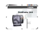
background image

532077-1EN_A

598ci HD SI Combo

Operations Manual

598ci HD SI Combo

Operations Manual

Summary of Contents for 500 series

Page 1: ...532077 1EN_A 598ci HD SI Combo Operations Manual 598ci HD SI Combo Operations Manual ...

Page 2: ... in your Humminbird unit is an aid to navigation designed to facilitate the use of authorized government charts not to replace them Only official government charts and notices to mariners contain all of the current information needed for the safety of navigation and the captain is responsible for their prudent use WARNING Disassembly and repair of this electronic unit should only be performed by a...

Page 3: ...cil of 27 January 2003 on the restriction of the use of certain hazardous substances in electrical and electronic equipment 500 Series Down Imaging DualBeam PLUS Fish ID Humminbird HumminbirdPC LakeMaster RTS RTS Window Side Imaging Structure ID SwitchFire UniMap WhiteLine X Press Menu and Xtreme Depth Series are trademarked by or registered trademarks of Johnson Outdoors Marine Electronics Inc Ba...

Page 4: ...Instant Image Update 11 Sonar Colors and Bottom View 12 What s on the Side Imaging Display 14 Understanding the Side Imaging Display 16 Side Imaging Frequencies and Coverage 18 For Best Performance 18 On the Water Interpretation 20 What s on the Down Imaging Display 24 Understanding the Down Imaging Display 26 Interpreting the Display 26 Down Imaging Sensitivity 27 Freeze Frame and Active Cursor 2...

Page 5: ...entation 59 Viewing Cartography 60 Introduction to Navigation 62 Waypoints Routes and Tracks 62 Open the Waypoint Management Dialog Box 64 What s on the Waypoint Management Dialog Box 65 Save Create or Delete a Waypoint 67 Navigate to a Waypoint or Position 68 Add a Waypoint Target or Trolling Grid 69 Routes 70 Tracks 72 Edit your Waypoints Routes Tracks and Groups 73 Man Overboard MOB Navigation ...

Page 6: ...ion Data 85 Update Software 87 The Menu System 88 Start Up Options Menu 89 Normal 89 Simulator 90 System Status 90 Self Test 91 Accessory Test 91 GPS Diagnostic View 92 X Press Menu 93 Main Menu 94 Quick Tips for the Main Menu 95 Note for all Menu Settings 95 User Mode Normal or Advanced 96 Sonar X Press Menu Sonar Views only 98 Cancel Navigation only when Navigating 99 Sensitivity 99 Table of Con...

Page 7: ...gating 103 SI Side 103 SI Sensitivity 103 SI Enhance 104 SI Range 105 Chart Speed 105 Imaging Colors 105 Down Imaging X Press Menu Down Imaging Views only 106 Cancel Navigation only when Navigating 107 Down Sensitivity 107 DI Enhance 107 Upper Range Advanced 108 Lower Range 109 Chart Speed 109 Imaging Colors 109 Flasher X Press Menu Circular Flasher View only 110 Cancel Navigation only when Naviga...

Page 8: ...igation X Press Menu Navigation Views only 118 Cancel Navigation only when Navigating 119 Cancel MOB Navigation only when MOB Navigation is activated 119 Skip Next Waypoint only when Navigating 119 Waypoint Name only with an active cursor on a waypoint 119 Cursor To Waypoint Chart or Chart Combo Views only 120 Chart Declutter 120 Save Current Track 120 Clear Current Track 121 Save Current Route on...

Page 9: ...her View Big Digits View and Sonar Combo Views 133 Bottom View 133 Zoom Width 134 83 kHz Sensitivity Advanced 134 Depth Lines Advanced 134 SI Range Lines Advanced Side Imaging View only 135 Noise Filter Advanced 136 Max Depth Advanced 136 Water Type Advanced 137 Connected Transducer 137 Down Imaging Beam Width Advanced Down Imaging Views only 138 Ice Fishing Mode 138 Navigation Menu Tab 139 Curren...

Page 10: ...I Navigation Side Imaging Views only 146 Chart Menu Tab 147 Lat Lon Grid 148 Navaids on Bird s Eye View 148 Chart Select 148 Set Simulation Position Advanced 148 Set Map Offset Advanced 149 Clear Map Offset Advanced 149 Shaded Depth 149 Chart Detail Level 150 Map Borders 151 Spot Soundings 152 Auto Zoom Advanced 152 Auto Range Advanced 152 Vessel Offset Advanced 152 Offset Speed with Vessel Offset...

Page 11: ...er Mode 157 Language International Models only 158 Triplog Reset 158 Restore Defaults 158 Format Nav Directories 158 Select Readouts Advanced Sonar View and Down Imaging View only 159 Depth Offset Advanced 160 Temp Offset Advanced with Temp Speed only 160 Speed Calibration Advanced with Temp Speed only 160 Local Time Zone Advanced 160 Daylight Saving Time Advanced 161 Position Format Advanced 161 ...

Page 12: ...tional distributors please visit our Web site at humminbird com or contact our Customer Resource Center at 334 687 6613 NOTE Entries in this Table of Contents which list with Temp Speed only require the purchase of separate accessories Visit our Web site at humminbird com to order these accessories online or contact our Customer Resource Center at 1 800 633 1468 NOTE Some features discussed in thi...

Page 13: ... long to select a Start Up Option the system will default to whichever menu is already highlighted You can also select Simulator to learn how to use your control head and save settings in advance for later use 4 Quick Setup If this is the first time the unit has been powered on after installation or after restoring defaults the Quick Setup dialog box will display on the screen Use the 4 WAY Cursor...

Page 14: ...n size and composition of an object Sonar is very fast A sound wave can travel from the surface to a depth of 240 ft 70 m and back again in less than 1 4 of a second It is unlikely that your boat can outrun this sonar signal SONAR is an acronym for SOund and NAvigation Ranging Sonar utilizes precision sound pulses or pings which are emitted into the water in a teardrop shaped beam The sound pulses...

Page 15: ... provide a good balance between depth performance and resolution Low frequencies 83 kHz are typically used to achieve greater depth capability The power output is the amount of energy generated by the sonar transmitter It is commonly measured using two methods Root Mean Square RMS measures power output over the entire transmit cycle Peak to Peak measures power output at the highest points The bene...

Page 16: ...an area that is 240 feet wide to each side 480 feet total coverage with a depth limitation of 150 feet See What s on the Side Imaging Display and Understanding the Side Imaging Display for more information The Side Imaging transducer also provides down imaging displays on the screen See What s on the Down Imaging Display for more information Depth capability is affected by such factors as boat spe...

Page 17: ...our coverage to an area equal to your depth In 20 feet of water the wider beam covers an area 20 feet wide DualBeam PLUS sonar returns can be blended together viewed separately or compared side by side DualBeam PLUS is ideal for a wide range of conditions from shallow to very deep water in both fresh and salt water Depth capability is affected by such factors as boat speed wave action bottom hardn...

Page 18: ...efinition The 20 center beam provides the highest definition while the 60 beam provides wider coverage Depth capability is affected by such factors as bottom hardness and water conditions Whether fishing in shallow or very deep water selectable dual frequency is ideal for a variety of conditions NOTE Contact our Customer Resource Center to determine which accessory transducers are compatible with ...

Page 19: ...er civilians may also take advantage of its highly accurate position capabilities typically within 4 5 meters depending on conditions This means that 95 of the time the GPS receiver will read a location within 4 5 meters of your actual position Your GPS Receiver also uses information from WAAS the Wide Area Augmentation System EGNOS the European Geostationary Navigations Overlay Service and MSAS t...

Page 20: ... SecondSonarReturn Whenthesonarsignal bounces between the bottom and the surface of the water and back again Use the appearance of the second return to determine bottom hardness Hard bottoms will show a strong second return while soft bottoms will showaveryweakoneornoneatall Speed If a GPS Receiver or Temp Speed accessory is connected the Fishfinder can display the speed of the boat and can keep a...

Page 21: ...lay at the same depth Bait Ball Fish The Fishfinder displays fish as arches and or fish icons and can be set to alarm when a fish of a certain size is detected When a target is detected a Fish ID symbol appears on the display with the depth displayed above it The size of the symbol indicates the intensity of the sonar return The unit will clearly show schools of Bait Fish as clouds of different sh...

Page 22: ... Time Sonar RTS Window appears on the right side of the display in the Sonar View only The RTS Window updates at the fastest rate possible for depth conditions and shows only the returns from the bottom structure and fish that are within the transducer beam The RTS Window plots the depth and intensity of a sonar return see Sonar Menu Tab RTS Window The Narrow RTS Window indicates the sonar intensi...

Page 23: ... Cursor Press any arrow on the 4 WAY Cursor Control key and the screen will freeze and a cursor will be displayed Use the 4 WAY Cursor Control key to move the cursor over a sonar return and the depth of the sonar return will be displayed at the bottom of the screen in the cursor dialog box The RTS Window continues to update in Freeze Frame To return to a scrolling display and exit Freeze Frame pre...

Page 24: ...n and small fish The colors used to represent high medium to low intensity returns are determined by the palette you choose in the Sonar Colors menu option See Sonar Menu Tab to set the Sonar Colors Sonar View Original Palette Strong Returns possibly rocks tree limbs or other structure Weak Returns possibly vegetation or small fish RTS Window Sonar History Historical Returns scroll left across the...

Page 25: ...in red when Sonar Colors is set to Original If the Sonar Colors palette is changed the Structure ID will display the strongest return as specified by the palette See Sonar Menu Tab Sonar Colors for more information WhiteLine highlights the strongest sonar returns in white resulting in a distinctive outline This has the benefit of clearly defining the bottom on the display What s on the Sonar Displ...

Page 26: ...Boat Icon Top of the Display Information from the side beams are displayed at the top of the screen As new information is received the historical data scrolls down the screen The boat icon will turn to indicate the direction of navigation The water column shows the relative depth of the water under the boat at a given time Variations in the width of the water column show variations in the distance...

Page 27: ... object or the depth to which it has sunk into the bottom through shadows on the display Objects standing on the bottom cast a sonar shadow The longer the shadow the taller the object Fish also cast shadows You can use the shadow to interpret how close the fish is to the bottom Side Imaging Range Images shown on the right side of the screen are located on the right side of your boat and images sho...

Page 28: ...n from front to back yet very wide top to bottom The narrow aspect front to back of the beam illuminates a small strip of the bottom perpendicular to the direction of the boat Each time the unit pings a strip of data representing all the echoes received by the transducer are put together on the display to form the image that you see The rows closest to the boat icon at the top of the view are the ...

Page 29: ...ltwater anglers pick up precise details of popular fishing structure like wrecks reefs humps and drop offs as well as being able to spot bait balls in open water Freshwater anglers can see fish attracting structure such as timber stumps rocks and creek beds Side Imaging sonar echoes are first displayed at the top of the screen and historical data scrolls down the display as new information is rece...

Page 30: ...Beams are extremely narrow from front to back and provide thin slices of the bottom for high resolution imaging Side Imaging Range 240 feet to each side with a total side coverage of 480 feet with a depth limitation of 150 feet depending on the contour of the bottom and when the side beam frequency selection is set to 455 kHz The total coverage under the boat is 180 degrees For Best Performance Us...

Page 31: ...ion i e wave induced etc This applies to navigation by either the main engine or the trolling motor Minimize turning time and avoid wave action that induces large side to side rocking of the boat For example if there is a lot of wave activity try to move the boat so that it is perpendicular to the waves instead of parallel with the waves in order to minimize the side to side rocking of the boat Be...

Page 32: ...he Side Imaging Display On the Water Interpretation Submerged Ravine with Timber Submerged Timber Submerged Ravine Possible Drop Off Submerged Tree Creek Channel and New Bridge Piling New Bridge Pilings Creek Channel ...

Page 33: ...dge Alternative Perspective Submerged Bridge When there is an area directly under the boat that does not have Side Imaging coverage a single object may appear as two separate objects on the display Submerged Bridge A Closer Perspective Submerged Bridge ...

Page 34: ...22 What s on the Side Imaging Display Submerged Swimming Pool Swimming Pool Submerged Standing and Fallen Timber plus Bait Fish Bait Fish Standing and Fallen Timber ...

Page 35: ...23 What s on the Side Imaging Display Submerged Barge with Dumped Logs Dumped Logs Submerged Barge ...

Page 36: ...display indicates soft bottom sand mud or descending terrain BottomReturn Usetheappearanceofthebottom return to determine bottom hardness Rock and gravel provide a clearer sonar return than mud and sand because hard objects reflect sonar better than soft objects NOTE Entries in this view that list with Temp Speed or GPS Receiver are available if then only the information from the GPS receiver will...

Page 37: ...he bottom through shadows on the display Objects standing on the bottom cast a sonar shadow The longer the shadow the taller the object Fish also cast shadows You can use the shadow to interpret how close the fish is to the bottom Clouded Area may indicate a bait ball and White Streaks may indicate fish Lower Range Structure either device is connected to the 500 Series Fishfinder If both devices a...

Page 38: ...ont to back Use the light and dark parts of the display to interpret the objects under your boat as follows Dark shades represent soft returns mud sand or descending terrain Light shades represent denser terrain timber rocks or rising terrain A very hard bottom may appear as white on the display White Streaks or Clouds may represent fish on the display Shadows are not caused by light but by the la...

Page 39: ...Imaging X Press Menu for more information Freeze Frame and Active Cursor Freeze Frame and Active Cursor Press any arrow on the 4 WAY Cursor Control key and the screen will freeze and a cursor will be displayed Use the 4 WAY Cursor Control key to move the cursor over a sonar return and the depth of the sonar return will be displayed in the cursor dialog box Zoom Use the zoom feature on your control...

Page 40: ...ess the EXIT key the display cycles through the available views in reverse order Customize You can display or hide any view to suit your fishing preferences See the following pages for more information about each View To customize your views rotation You can choose which views are hidden or visible in your view rotation 1 Press the MENU key twice to access the tabbed Main Menu then press the RIGHT...

Page 41: ...then press the RIGHT Cursor key until the Setup tab is selected 2 Press the DOWN key to highlight Select Readouts and press the RIGHT Cursor key to access the Select Readouts submenu NOTE If the Select Readouts option does not appear under the Setup tab change the User Mode to Advanced 3 Press the UP or DOWN Cursor keys to select a Readout position then press the RIGHT or LEFT Cursor keys to choos...

Page 42: ...tion Freeze Frame Press any arrow on the 4 WAY Cursor Control key and the SI View will freeze and a cursor will appear on the screen Use the 4 WAY Cursor Control key to move the cursor over a sonar return and observe the following The depth of the sonar return at the cursor location will be displayed in the cursor information box Zoom Press the ZOOM key and a zoom box will appear and magnify the a...

Page 43: ...ion for more information Distance to the Cursor and Bearing to Cursor Magnification Sights Side Imaging View with Active SI Zoom SI Zoom Level Depth Magnification Box Distance of Cursor from Centerline Depth Shadows Side Imaging View Side Beam Range Water Column Bottom Return Orange Boat Icon navigating Topography Changes Speed Views ...

Page 44: ...e to access the Down Imaging X Press Menu You can set the sensitivity of the sonar the chart scrolling speed the display color palette and the Upper Range and Lower Range see Down Imaging X Press Menu Freeze Frame Press any arrow on the 4 WAY Cursor Control key and the Down Imaging View will freeze and a cursor will appear on the screen Use the 4 WAY Cursor Control key to move the cursor over a so...

Page 45: ...ng Display and Down Imaging X Press Menu for more information Down Imaging View White Streaks possibly vegetation or fish Lower Depth Range Surface Clutter Bottom Return Temperature Speed Depth Sonar History Window Upper Depth Range Views ...

Page 46: ...nge based on the Select Readouts settings or the optional purchase accessories attached see Setup Menu Tab Select Readouts Freeze Frame Use the 4 WAY Cursor Control key to freeze the display and move the cursor over a sonar return The depth of the sonar return will be displayed at the bottom of the screen in the cursor information box NOTE If the Depth number is flashing it means that the unit is ...

Page 47: ...ludes the Zoom Preview Box which shows where the zoomed view is in relation to the full range view The Upper and Lower Depth Range numbers indicate the high and low range of the water which is being viewed Freeze Frame Use the 4 WAY Cursor Control key to freeze the display and move the cursor over a sonar return The depth of the sonar return will be displayed at the bottom of the screen in the cur...

Page 48: ...ht side of the screen Depth is displayed in the upper left hand corner The Digital Readouts in the Split Sonar View cannot be customized therefore information such as water temperature and voltage are unavailable in the Split Sonar View Freeze Frame Use the 4 WAY Cursor Control key to freeze the display and move the cursor over a sonar return The depth of the sonar return will be displayed at the ...

Page 49: ...cted to the Fishfinder NOTE The digital readouts in the Big Digits View cannot be customized The Triplog shows distance traveled average speed and time elapsed since the Triplog was last reset Big Digits View Depth Temperature Speed Timer shows the time elapsed since Triplog was last reset Distance is the distance traveled since the Triplog was last reset Voltage displays the battery voltage Avera...

Page 50: ...ta in a traditional flasher format When Ice Fishing Mode is on the Circular Flasher View displays the sonar data in traditional flasher format with additional features including Zoom and Depth Cursor Set the Circular Flasher View Mode 1 Press the MENU key twice 2 Press the RIGHT Cursor key until the Sonar Menu Tab is selected 3 Press the DOWN Cursor Key to select Ice Fishing Mode Press the RIGHT o...

Page 51: ... a traditional flasher format Flasher X Press Menu Press the MENU key once in the Circular Flasher View Use the X Press Menu to set the Sensitivity Upper Range and Lower Range Depth and temperature are always displayed The Digital Readouts cannot be customized Circular Flasher View Ice Fishing Mode Off Flasher Dial Depth ...

Page 52: ...ss Menu Press the MENU key once in the Circular Flasher View Use the X Press Menu to set the Sensitivity Upper Range Lower Range and Color Palette Color Palettes The color preview bar in the center of the display indicates the current palette and the weak to strong sonar return range is displayed from left to right To change the color palette see Flasher X Press Menu Color Palette The Digital Read...

Page 53: ...ing Mode see Sonar Menu Tab 2 Activate Press the DOWN Cursor key and the purple cursor line will appear on the display 3 Adjust the Cursor Press the UP or DOWN Cursor keys repeatedly until you reach the chosen depth reading The depth reading of the cursor is displayed in the top right corner of the view 4 Close the Cursor Press the EXIT key Circular Flasher View with the Depth Cursor Depth Cursor ...

Page 54: ... will appear on the display 3 Adjust the Zoom Range Press the RIGHT or LEFT Cursor keys repeatedly to adjust the zoom range and select the area you want to magnify The zoomed view is shown on the right side of the flasher dial between two lines The normal view is shown on the left side of the flasher dial 4 Close Zoom Press the ZOOM key Circular Flasher Zoom Zoom Line lower limit Zoom Line upper l...

Page 55: ...to scroll through the saved Screen Snapshots and Recordings The active file is highlighted with arrows Press the RIGHT Cursor key to view the file Snapshot and Recording X Press Menu Press the MENU key once in this view to open the X Press Menu Use the X Press Menu to Start Recording Delete Images or adjust the Recording and Playback settings see Recording and Playback or Snapshot and Recording X ...

Page 56: ... saved A waypoint will also be created at the boat or active cursor location The screen snapshot shares the same file name PNG Delete a Screen Snapshot 1 From the Snapshot and Recording View press the UP or DOWN Cursor keys to scroll through the saved files and highlight a snapshot file 2 Press the MENU key once and select Delete Image from the X Press Menu 3 Press the RIGHT Cursor key NOTE Naviga...

Page 57: ... is a saved screen snapshot and not a live view If you press the CHECK INFO key and the snapshot file connected to the icon is not saved on the installed SD memory card the chart information box will display instead of the screen snapshot Use an optional purchase SD memory card reader connected to a PC to view the saved screen snapshot data files on your optional purchase SD memory card see hummin...

Page 58: ...d at the boat location and the recording shares the same file name SON Stop Recording 1 In any view press the MENU key once to open the Snapshot and Recording X Press Menu 2 Highlight Stop Recording and press the RIGHT Cursor key Notes about Recording While recording press the EXIT key to exit the Snapshot and Recording X Press Menu and scroll to a different view Recording will continue The slider...

Page 59: ... Snapshot and Recording X Press Menu 2 Highlight Stop Playback and press the RIGHT Cursor key Delete a Recording 1 From the Snapshot and Recording View press the UP or DOWN Cursor keys to scroll through the saved files and highlight a saved Recording 2 Press the MENU key once and select Delete Recording from the X Press Menu Press the RIGHT Cursor key From Snapshot and Recording View select Delete...

Page 60: ...the location you choose Press EXIT to resume Playback Press the MARK key during Playback to save a Screen Snapshot and or mark a waypoint in the view or active cursor location you choose When you save screen snapshots and recordings to an SD card a DAT or a TXT file is created for every PNG screen snapshot and a TXT file is created for every recording folder These data files are required for viewi...

Page 61: ...e eye point position so that you can look off to the sides or even behind the boat Press the RIGHT or LEFT Cursor keys to turn the eye point right or left Press the UP Cursor key to move the eye point forward and press the DOWN Cursor key to move the eye point backward Press the EXIT key to move the eye point back to its original position behind and above the boat Bird s Eye View Depth Speed of Bo...

Page 62: ...duction to Navigation for more information Shift Pan Use the 4 WAY Cursor Control key to shift pan the chart to another area Zoom Press the ZOOM keys to zoom in and out Zooming is also influenced by the Auto Zoom and Auto Range settings See Chart Menu Tab Auto Zoom and Auto Range for more information Info Press the CHECK INFO key to get information on the chart objects near the cursor Chart View w...

Page 63: ...e Cursor shown with Optional Purchase Navionics Cartography Cartography Active Cursor Bearing of Boat with Respect to True North Latitude and Longitude Position of Cursor Depth Map Scale Distance to the Cursor and Bearing to Cursor ...

Page 64: ...rsor Control key to shift pan the chart to another area You can mark waypoints start navigation review position information or magnify the view See Chart View and Introduction to Navigation for more information Sonar Window To change the width of the Sonar Window press the MENU key once and select Sonar Window from the X Press Menu Press the RIGHT or LEFT Cursor keys to select a setting Combo View...

Page 65: ...and Side Imaging X Press Menu for more information about the menu options Chart Window Use the 4 WAY Cursor Control key to shift pan the chart to another area You can mark waypoints start navigation review position information or magnify the view See Chart View and Introduction to Navigation for more information Depth Boat Icon Chart Side Combo View Water Surface Temperature Course the current dir...

Page 66: ...rmation about the menu options Chart Window Use the 4 WAY Cursor Control key to shift pan the chart to another area You can mark waypoints start navigation review position information or magnify the view See Chart View and Introduction to Navigation for more information Down Imaging Window To change the width of the Down Imaging Window press the MENU key once and select Sonar Window from the X Pre...

Page 67: ...ess the X Press Menu for this combo view You can set the sensitivity of the sonar the chart scrolling speed and the display color palette see Down Imaging X Press Menu and Side Imaging X Press Menu Freeze Frame Use the 4 WAY Cursor Control key to move the cursor over a sonar return in the Down Imaging View and the depth of the sonar return will be displayed in the cursor dialog box Depth Down Side...

Page 68: ... Press the MENU key once to access the Down Imaging X Press Menu See Side Imaging X Press Menu and Sonar X Press Menu for more information about the menu options in this combo view Freeze Frame Use the 4 WAY Cursor Control key to move the cursor over a sonar return in the Sonar View and the depth of the sonar return will be displayed in the cursor dialog box Depth Lower Depth Range Sonar Side Comb...

Page 69: ... the sensitivity of the sonar the chart scrolling speed and the display color palette see Down Imaging X Press Menu and Sonar X Press Menu Freeze Frame Press any arrow on the 4 WAY Cursor Control key and the view will freeze and a cursor will appear on both views on the screen Use the 4 WAY Cursor Control key to move the cursor over a sonar return and the depth of the sonar return will be displaye...

Page 70: ... and Sonar X Press Menu for more information about the menu options in this combo view Freeze Frame Press any arrow on the 4 WAY Cursor Control key and the view will freeze and a cursor will appear at the same time in the Sonar View and Down Imaging View Use the 4 WAY Cursor Control key to move the cursor over a sonar return and the depth of the sonar return will be displayed in the cursor dialog ...

Page 71: ...o that the vessel always points up on the view Course Up During navigation the projected course is shown at the top of the view Objects ahead of the boat are drawn above the boat When the boat is not navigating the course up reference is provided by the COG course over ground calculation Also to display the north icon on the view see Navigation Menu Tab North Up Indicator North Up Icon If it is tu...

Page 72: ...ilable chart data is amplified to reflect the level selected If you zoom in so far that no cartography is available a lat long grid will be drawn instead Zooming is also influenced by the Auto Zoom and Auto Range settings See Chart Menu Tab Auto Zoom and Auto Range for more information Decluttered Waypoints When two or more waypoints overlap or are displayed close together on a chart view the scre...

Page 73: ...or the 24 hour time period encompassing the date You can change the date to look at tide information before or after the date displayed by pressing the LEFT or RIGHT Cursor key respectively Press the EXIT key to remove the information box and the cursor bull s eye will be centered over the tide station position The cursor information boxes at the bottom of the display indicate the distance and bea...

Page 74: ...r Fishfinder can store up to 2 750 waypoints Routes link two or more waypoints together to create a path for navigation and are used in trip planning You can link individual waypoints together by using the GOTO key Your Fishfinder can store up to 45 routes that can each contain up to 50 waypoints Waypoints Routes and Tracks Track Future Route Leg gold BRG Bearing to the next Waypoint XTE Cross Tra...

Page 75: ...oute Leg Gold Tracks consist of detailed position history and are displayed as a breadcrumb trail of trackpoints The Current Track shows the position history since the unit was powered up You can clear the Current Track or save it at any time Your Fishfinder can store up to 50 saved tracks each containing 20 000 trackpoints The current track represents your actual path so far NOTE The maximum numb...

Page 76: ...ad Open the Waypoint Management Dialog Box 1 Press the MENU key twice to open the Main Menu 2 Press the RIGHT Cursor key until the Navigation Menu Tab is selected 3 Press the DOWN Cursor key to choose Waypoints Routes Tracks Press the RIGHT Cursor key to open the Waypoint Management dialog box Opening the Waypoint Management Dialog Box Introduction to Navigation ...

Page 77: ...key To move to the higher level group or the higher level directory press the LEFT Cursor key As you scroll through the Waypoint Management dialog box press the EXIT key to select the Options menu quickly Press the EXIT key twice to close the dialog box Sort By Select Sort By and press the RIGHT Cursor key repeatedly to choose a sorting option for the waypoints routes tracks and groups A Z Z A New...

Page 78: ...s field also changes to display instructions Directory Shows the directory structure and the currently selected group The illustration shows group GP070 as the selected group Arrows When arrows are displayed on a menu option additional information or submenus are available If the arrow points to the right press the RIGHT Cursor key If the arrow points to the left press the LEFT Cursor key to move ...

Page 79: ... record the depth at that location Create a New Waypoint To create a waypoint that is NOT your current position open the Waypoint Management dialog box Select Options New New Waypoint Use the 4 WAY Cursor Control key to set the available fields See Edit your Waypoints Routes Tracks and Groups for details Delete a Waypoint Open the Waypoint Management dialog box Select a Waypoint and press the RIGH...

Page 80: ...ment dialog box Select a Waypoint and press the RIGHT Cursor key to open the Waypoint submenu Select Go To and press the RIGHT Cursor key Skip a Waypoint From the Navigation X Press Menu select Skip Next Waypoint and press the RIGHT Cursor key If there is not another waypoint to skip to navigation will be canceled Cancel Navigation From the Navigation X Press Menu select Cancel Navigation and pres...

Page 81: ...he RIGHT Cursor key The grid can also be rotated to any heading by adjusting the Grid Rotation setting on the Navigation Main Menu Remove Target or Trolling Grid Press the MENU key once and choose Remove Target or Remove Grid from the Navigation X Press Menu and press the RIGHT Cursor key NOTE Only one waypoint can have either a target or a grid applied to it at one time If you apply a target or a...

Page 82: ...n Route Select Plan Route and press the RIGHT Cursor key The New Route dialog box closes so that you can select waypoints from the Waypoint Management dialog box To add a selected waypoint to the route press the RIGHT Cursor key Repeat as needed Select Save and press the RIGHT Cursor key Adding Waypoints to a Route A confirmation displays each time you add a waypoint to the Route New Route Informa...

Page 83: ...of the following options Select Reverse and press the RIGHT Cursor key This will quickly reverse the order of the route Press the EXIT key to select Save Press the RIGHT Cursor key to confirm your changes OR Choose a Waypoint in a route and press the RIGHT Cursor key Select Reorder and press the RIGHT Cursor key To move the waypoint up or down in the route order press the UP or DOWN Cursor keys Pr...

Page 84: ...a track a name is automatically assigned The track name consists of a date time stamp but can be re named later see Edit your Waypoints Routes Tracks and Groups Clear the Current Track From the Navigation X Press Menu select Clear Current Track and press the RIGHT Cursor key The track will be removed from the display and permanently deleted Hide or Display a Saved Track Open the Waypoint Managemen...

Page 85: ...gs will depend on the type of item you are editing NOTE The Edit Waypoint dialog box is also available when you select a waypoint from the Navigation X Press Menu NOTE See your Humminbird Waypoint Management Guide for more information about groups and the other great features of the Waypoint Management dialog box Visible on Chart View Hidden on Chart View Editing a Waypoint Introduction to Navigat...

Page 86: ...l as digits 0 9 and some punctuation symbols Icon Category Press the UP or DOWN Cursor keys to scroll through the available categories Select All to view all available icons All Geometry Alerts Supplies Navigation Recreation Fish Environment Icon Press the UP or DOWN Cursor keys to scroll through the available icons used to represent the waypoint in Chart View The available icons are determined by...

Page 87: ...n will be cancelled and the current route will be discarded without user notification MOB navigation will begin immediately and the MOB View will show the following The view will switch to the Chart View and the elapsed time since MOB was activated will be displayed A line will be drawn from the boat s current position to the MOB waypoint and the MOB waypoint will be targeted The latitude longitud...

Page 88: ... the GOTO key but does not remove any saved routes from memory It is not possible to re activate MOB or modify the current route without first canceling MOB navigation The Off Course trigger is also disabled and the Off Course Alarm circle is not drawn Any press of the GOTO key or selection of a GOTO menu option will cause an error beep and a short message will be displayed that will disappear aft...

Page 89: ...isplay Refer to the following illustration and see Key Functions for more information Your control head will have one of the CHECK INFO keys shown here Both keys function in the same way Screen MENU key 1 7 MARK key 8 CHECK INFO key EXIT key 2 9 GOTO key 10 3 4 5 6 7 8 9 10 1 POWER LIGHT key 11 SD Card slot cover 12 VIEW key ZOOM key 3 5 4 WAY Cursor Control key LEFT RIGHT UP or DOWN Cursor keys 6...

Page 90: ...r 3 seconds A message will appear to indicate how many seconds there are until shutdown occurs To ensure that shutdown occurs properly and any menu settings will be saved your Fishfinder should always be turned off using the POWER LIGHT key Adjust the Backlight or the Display Background Color Press the POWER LIGHT key to access the Light and Background submenu Use the 4 WAY Cursor Control key to s...

Page 91: ...rt Info submenu will be displayed See Views Viewing Cartography for more information NOTE Your control head will have one of the keys shown here Both keys function in the same way MENU Key The MENU key is used to access the menu system See The Menu System for more information Start Up Options Menu Press the MENU key during the power up sequence to view the Start Up Options menu X Press Menu Press ...

Page 92: ...ation you choose Active Cursor Press any arrow on the 4 WAY Cursor Control key and the active cursor will appear on the screen Chart Views Press any arrow on the 4 WAY Cursor Control key to pan the chart and highlight decluttered waypoint icons Bird s Eye View The 4 WAY Cursor Control key controls the motion of the eye point Snapshot and Recording View Press the UP or DOWN Cursor keys to highlight...

Page 93: ...ey will capture the screen image and display an error saying that a GPS position fix is required to create a waypoint NOTE You must have an optional purchase SD memory card installed for the screen snapshot feature to work GOTO Key The GOTO key has multiple functions depending on the situation Active Cursor Press the GOTO key while in any view to create a waypoint and start navigation towards that...

Page 94: ...lection Press the Zoom key to decrease the scale NOTE The cursor must be active for the zoom feature to work in the Side Imaging or Down Imaging View EXIT Key The EXIT key has multiple functions depending on the situation If an alarm is sounding press the EXIT key to cancel the alarm If a menu tab is selected press the EXIT key to exit the menu mode and return to the view If a menu is active press...

Page 95: ...n on the card until it clicks into place 3 Close the slot cover and turn the knob just 1 4 of a turn to close Do NOT overtighten as this will not improve water resistance and may damage the cover 4 To Remove Press the SD memory card into the slot and then release The card will eject and you can then pull the card from the slot NOTE Do not leave the SD slot cover open The slot cover should always b...

Page 96: ...e Chart Select menu option in the Chart Menu Tab see Chart Menu Tab Chart Select Chart Layers You can customize your Navigation Views by selecting which chart layers to display or hide see Chart Menu Tab Chart Detail Level Map Borders Use the 4 WAY Cursor Control key to move the active cursor within a map border and press the ZOOM key to view the different map see Chart Menu Tab Map Borders Menu O...

Page 97: ...ment dialog box allows you to export all of your navigation items to an installed unlocked SD Card You can also export selected items For more information see Introduction to Navigation What s on the Waypoint Management Dialog Box Also see your Humminbird Waypoint Management Guide for complete details It is important to back up your control head s data files waypoints routes tracks groups recordin...

Page 98: ...the Navigation tab is selected Select Waypoints Routes Tracks Press the RIGHT Cursor key 3 From a selected group directory in the Waypoint Management dialog box select Options Select Multiple and Export 4 Select Items Press the UP or DOWN Cursor keys to scroll through the waypoints routes tracks and groups Press the RIGHT Cursor key to select an item Repeat as needed 5 Confirm Export When you are ...

Page 99: ...connected to your PC 2 Register your Fishfinder Log on to humminbird com Click My Account Set up a new account 3 Download From My Account My Profile My Equipment click the file name of the latest software update unit name version Read the instructions in the dialog box and click Download Follow the prompts to save the software file directly to the SD Card 4 Install the SD card with the updated sof...

Page 100: ...l Simulator and System Status X Press Menu The X Press Menu provides a shortcut to the most frequently used settings and the options on the X Press Menu correspond with the current view Main Menu The Main Menu is a standard set of menu settings which are organized under the following tabbed headings Alarms Sonar Navigation Chart Setup and Views NOTE The X Press Menu s and the Main Menu options can...

Page 101: ... following pages Also see Power On for additional information Normal Use Normal for on the water operation with a transducer connected If a functioning transducer is connected Normal operation will be selected automatically at power up and your Fishfinder can be used on the water To exit Normal operation power off your Fishfinder Start Up Options Menu ...

Page 102: ...portant to select Simulator manually from the Start Up Options Menu as opposed to letting the Fishfinder enter Simulator automatically as it will if a transducer is not connected and you do nothing during power up A message will appear often on the display to indicate Simulator mode To exit Simulator power off your Fishfinder System Status Use System Status to view system connections and to conduc...

Page 103: ...Board PCB serial number software revision total hours of operation and the input voltage Accessory Test lists the accessories connected to the system NOTE The speed accessory will be detected only if the paddlewheel has moved since your Fishfinder was powered up Accessory Test Self Test Screen Start Up Options Menu ...

Page 104: ...yet being used This view also reports the current position local time and date and other numeric information The current GPS Fix Type is reported as No Fix 2D Fix 3D Fix or Enhanced An Enhanced fix has been augmented using information from WAAS EGNOS or MSAS A 3D or Enhanced Fix is required for navigation HDOP the Horizontal Dilution of Precision is a GPS system parameter which depends on the curr...

Page 105: ...n press the RIGHT or LEFT Cursor keys to change the menu setting NOTE The X Press Menu will collapse temporarily and the screen will update if it is affected by your menu setting change which allows you to see the effects of your change immediately 3 Reactivate the X Press Menu by pressing the UP or DOWN Cursor keys Total Screen Update When you change any menu settings that affect the current view...

Page 106: ... or LEFT Cursor keys to highlight a menu tab 3 Press the DOWN or UP Cursor keys to select a specific menu option under that tab 4 Press the RIGHT or LEFT Cursor keys to change a menu setting A down arrow at the bottom of a menu means that you can scroll to additional menu options using the DOWN Cursor key A right or left arrow on a menu option means that you can use the RIGHT or LEFT Cursor keys t...

Page 107: ...re information If you press the MENU key or EXIT key to leave the Main Menu and then return to the Main Menu at a later time the menu will open to the same tab as the last time the Main Menu was displayed Note for all Menu Settings The settings in all menus are adjusted in the same way Simply use the 4 WAY Cursor Control key to highlight a menu option and then change the settings or activate the o...

Page 108: ...ange the User Mode setting 1 Press the MENU key twice to access the Main Menu 2 Press the RIGHT Cursor key until the Setup tab is selected 3 Press the DOWN Cursor key to highlight User Mode on the Setup main menu 4 Press the LEFT or RIGHT Cursor keys to change the User Mode setting Normal Advanced Default Normal NOTE Any changes made while in Advanced Mode will remain in effect after you switch ba...

Page 109: ...97 Main Menu Sonar Tab Normal Mode Sonar Tab Advanced Mode ...

Page 110: ...ce while in any of the Sonar Views to access the Sonar X Press Menu NOTE Menu options can be expanded or simplified by setting the Fishfinder User Mode to Advanced or Normal See Main Menu User Mode for details NOTE Transducer selection also influences menu options see Sonar Menu Tab Connected Transducer Sonar X Press Menu Sonar X Press Menu ...

Page 111: ...itivity of all sonar frequencies When operating in very clear water or greater depths increase the sensitivity to see weaker returns that may be of interest If the sensitivity is adjusted too high the display may become too cluttered Decrease the sensitivity to eliminate the clutter from the display that is sometimes present in murky or muddy water If Sensitivity is adjusted too low the display ma...

Page 112: ...particular depth M will be displayed in the lower right corner of the screen to indicate the unit is in Manual mode Adjust the Upper and Lower Range together to view a specific depth range especially when looking for fish or bottom structure NOTE A minimum distance of 10 feet will be maintained between the Upper and Lower Range regardless of the manual settings entered For example if you are fishi...

Page 113: ...hanges the mode of the zoomed view in the Sonar Zoom View Bottom Lock continuously graphs the bottom at a constant point on the display regardless of changes in depth This flattens out the bottom contour but is effective at showing fish on or near the bottom Bottom Range Sonar Zoom View only when Bottom Lock is On Settings 10 to 60 feet 2 to 10 fathoms or 3 to 20 meters International Models only D...

Page 114: ...ost frequently used settings Press the MENU key once while in any of the Side Imaging Views to access the Side Imaging X Press Menu NOTE Menu options can be expanded or simplified by setting the User Mode to Advanced or Normal See Main Menu User Mode for details Side Imaging X Press Menu Side Imaging X Press Menu ...

Page 115: ...o 20 where Low 1 High 20 Default 10 SI Sensitivity controls how much detail is shown on the display Increase the SI Sensitivity to reveal weaker returns that may be of interest especially in very clear water or greater depths A high SI Sensitivity setting shows more sonar returns from small baitfish and suspended debris in the water however if the SI Sensitivity is adjusted too high the display ma...

Page 116: ...he clutter from the display that is sometimes present in murky or muddy water 1 to 20 where Low 1 High 20 Default 10 NOTE The Sensitivity can be adjusted from the SI Enhance dialog box or the Side Imaging X Press Menu The Sensitivity setting is provided here so that you can easily adjust the Side Imaging data with the other settings See Side Imaging X Press Menu SI Sensitivity for more information...

Page 117: ... the Side Imaging views The range must be set manually Chart Speed Settings 1 10 where 1 Slow 10 Fast Default 5 Chart Speed determines the speed at which the side sonar information moves down the display and consequently the amount of detail shown A faster speed shows more information in the Side Imaging Views and is preferred by most anglers however the sonar information moves across the display ...

Page 118: ...ost frequently used settings Press the MENU key once while in any of the Down Imaging Views to access the Down Imaging X Press Menu NOTE Menu options can be expanded or simplified by setting the User Mode to Advanced or Normal See Main Menu User Mode for details Down Imaging X Press Menu Down Imaging X Press Menu ...

Page 119: ...mall baitfish and suspended debris in the water however if the Down Imaging Sensitivity is adjusted too high the display may become too cluttered Decrease the Down Sensitivity to eliminate the clutter from the display that is sometimes present in murky or muddy water If the Down Imaging Sensitivity is adjusted too low the display may not show many sonar returns that could be fish DI Enhance Settin...

Page 120: ...efinition 1 to 20 Default 10 Sharpness Filters the view and sharpens the edges of the Down Imaging data Low L Medium M High H Default Off Upper Range Advanced Settings 0 to 1490 feet 0 to 497 meters International Models only Default 0 Upper Range sets the shallowest depth range that will be displayed on the Down Imaging Views Upper Range is often used with Lower Range NOTE A minimum distance of 10...

Page 121: ...ault 5 Chart Speed determines the speed at which the sonar information moves across the display and consequently the amount of detail shown A faster speed shows more information and is preferred by most anglers however the sonar information moves across the display quickly A slower speed keeps the information on the display longer but the bottom and fish details become compressed and may be diffic...

Page 122: ...e Flasher X Press Menu NOTE Menu options will vary depending on system settings such as whether you are currently navigating NOTE Menu options can be expanded or simplified by setting the User Mode to Advanced or Normal See Main Menu User Mode for details NOTE To activate Ice Fishing Mode see Sonar Menu Tab Also see Views Circular Flasher View for more information Flasher X Press Menu Flasher X Pr...

Page 123: ...f interest If the sensitivity is adjusted too high the display may become too cluttered Decrease the sensitivity to eliminate the clutter from the display that is sometimes present in murky or muddy water If Sensitivity is adjusted too low the display may not show many sonar returns that could be fish NOTE The Sensitivity setting is a global setting and will adjust the sensitivity of all sonar fre...

Page 124: ...ss of the manual settings entered Color Palette Circular Flasher View Ice Fishing Mode only Settings Palette 1 Palette 2 Palette 3 Default Palette 3 Color Palette sets the colors used to display sonar returns in the Circular Flasher View when Ice Fishing Mode is turned on The active color palette is shown in the center of the circular flasher display The color palettes range from weak to strong so...

Page 125: ...ovides access to the snapshot management and sonar recording functions Press the MENU key once while in the Snapshot and Recording View to access the Snapshot and Recording X Press Menu NOTE For more information see Views Snapshot and Recording View Snapshot and Recording X Press Menu Snapshot Recording X Press Menu ...

Page 126: ...installed and the control head is actively recording Delete Image optional purchase SD Memory Card only Settings Press the RIGHT Cursor key and follow screen instructions Delete Image allows you to delete a single screen capture image This menu option is only available when an optional purchase SD memory card is installed Snapshot and Recording View is on the screen and you have selected an image ...

Page 127: ...D memory card is installed and Snapshot and Recording View is on the screen Pings Per Second optional purchase SD Memory Card only Settings 1 to 10 Auto Default Auto Pings Per Second allows you to specify the ping rate for an active sonar recording NOTE Pings Per Second is available when an optional purchase SD memory card is installed Snapshot and Recording View is on the screen and the control h...

Page 128: ...d Recording Playback is active NOTE You can also change playback speed in the Snapshot and Recording View using the LEFT and RIGHT Cursor keys although you cannot skip to the beginning or end of a recording using these keys NOTE Sonar chart speed is increased during Fast Forward and reversed during Rewind This may result in a reduced quality sonar image since at higher speeds not every sonar retur...

Page 129: ...back of a sonar recording from any view This menu option is only available when an optional purchase SD memory card is installed and Recording Playback is active NOTE During playback the amount of time memory left to play is indicated by the status bar For more information see Views Snapshot and Recording View Snapshot Recording X Press Menu ...

Page 130: ...t or Chart Combo Views to access the Navigation X Press Menu NOTE Menu options will vary depending on system settings such as whether you are currently navigating NOTE Menu options can be expanded or simplified by setting the User Mode to Advanced or Normal See Main Menu User Mode for details See Introduction to Navigation and the Humminbird Waypoint Management Guide for more information Navigatio...

Page 131: ...n will only appear when you are currently navigating in Man Overboard Mode Skip Next Waypoint only when Navigating Settings Press the RIGHT Cursor key and follow screen instructions Skip Next Waypoint removes the next waypoint from the current route This menu option will only appear when you are currently navigating a route Waypoint Name only with an active cursor on a waypoint Settings Edit Delet...

Page 132: ...art Declutter Settings Press the RIGHT Cursor key to activate Chart Declutter removes all chart layers except for land outlines waypoints routes and tracks The chart will stay decluttered for 10 seconds and then it will refresh to its previous display settings To refresh the view faster than 10 seconds press the Zoom keys NOTE See Chart Menu Tab Chart Detail Level for more information Save Current...

Page 133: ...route Sonar Window Combo View and Chart Down Combo View only Settings Wide Medium Narrow Default Medium Sonar Window sets the size of the Sonar Window in the Combo View Reset XTE only when Navigating Settings Press the RIGHT Cursor key to activate Reset XTE is available during navigation When it is selected the cross track error XTE will be recalculated from the boat s current position to the next...

Page 134: ...re information Waypoint Name Most recently created waypoint Settings Edit Delete Go To Target Grid Waypoint Name allows you to view the waypoints submenu for the most recently created waypoint You must have pressed the MARK key at least once since you last powered up the Fishfinder for this menu option to appear NOTE See Introduction to Navigation and the Humminbird Waypoint Management Guide for m...

Page 135: ...en an alarm is triggered you can silence it by pressing any key The alarm will be silenced and will not be triggered again until a new instance of the alarm condition is detected NOTE Menu options can be expanded or simplified by setting the User Mode to Advanced or Normal See Main Menu User Mode for details Alarms Menu Alarms Menu Tab ...

Page 136: ... Alarm sounds when the input battery voltage is equal to or less than the menu setting The battery alarm will only sound for the battery that is connected to the Fishfinder The Low Battery Alarm should be set to warn you when the battery voltage drops below the safety margin that you have determined For instance if you are running a trolling motor battery operated set the Low Battery Alarm to soun...

Page 137: ...odels only Off Course Alarm Settings Off 25 to 3000 feet 10 to 1000 meters International Models only Default 300 ft 100 m Off Course Alarm allows you to set how far the boat is allowed to move off course before the Off Course Alarm will sound during navigation Arrival Alarm Circle Off Course Limits For example if the Temp Alarm is set to 58 degrees Fahrenheit and the water temperature falls from 6...

Page 138: ...t before the Arrival Alarm will sound Drift Alarm Settings Off 25 to 3000 feet 10 to 1000 meters International Models only Default Off Drift Alarm allows you to set the size of a perimeter around the boat s anchored position If the anchored boat drifts outside of that perimeter the Drift Alarm will sound Alarm Tone Settings High Medium Low Default Medium Alarm Tone selects the pitch of the alarm s...

Page 139: ...RIGHT Cursor key Save and Close To save your settings and start the Timer at a later time select Save and Close and press the RIGHT Cursor key Also see Start Timer Digital Readout To display the Timer on screen as it counts down see Views To Change the Digital Readouts Start Timer Settings Press the RIGHT Cursor key to start the Timer Start Timer allows you to start the Timer using the saved count...

Page 140: ...he Sonar tab is selected NOTE Menu options can be expanded or simplified by setting the User Mode to Advanced or Normal See Main Menu User Mode for details NOTE The selected transducer also influences the menu options See Sonar Menu Tab Connected Transducer for more information Sonar Menu Advanced Sonar Menu Tab ...

Page 141: ...igits View The RTS Window in the Sonar View and the Circular Flasher View will only show the returns from the 200 kHz narrow beam When set to 200 kHz only the returns from the 200 kHz narrow beam will be displayed in the Sonar View the Sonar Zoom View the Big Digits View and the Circular Flasher View The Split Sonar View will continue to display returns from both beams in their respective windows ...

Page 142: ...raw sonar returns on the display When Max Mode is selected you will see the maximum sonar information available within the transducer beam so more fish arches and better jig tracking are shown Choose Clear Mode to see less clutter and more fish size accuracy on the display When Clear Mode is selected the clutter is filtered and sonar returns are interpreted to provide more details about the object...

Page 143: ...ymbols and targets detected in the 83 kHz wide beam are represented as blue fish symbols When Fish ID is turned off the Fishfinder shows only the raw sonar returns on the display These returns will often result in arches forming on the display indicating potential targets Due to the transducer beam angle the distance to a fish decreases as the fish moves into the beam and then increases as it move...

Page 144: ...ecies of fish Fish ID Sensitivity is used in conjunction with Fish ID Fish ID must be on for Fish ID Sensitivity to affect the ability of the Fishfinder to identify sonar returns as fish Real Time Sonar RTS Window Settings Wide Narrow Off Default Narrow RTS Window sets the RTS Window to either Wide or Narrow or turns it off in the Sonar View The RTS Window always updates at the fastest rate possib...

Page 145: ...lue weak Purple medium Yellow strong Palette 2 Navy Blue weak Green medium Yellow strong Palette 3 Navy Blue weak to Red strong NOTE To change the color palette for the Circular Flasher View see Flasher X Press Menu Color Palette Bottom View Settings Structure ID WhiteLine Default Structure ID Bottom View selects the method used to represent bottom and structure on the display Structure ID represe...

Page 146: ...r weak returns NOTE 83 kHz Sensitivity is particularly useful for adjusting the sensitivity of the 83 kHz sonar returns in the 200 83 kHz Split Sonar View The 83 kHz sensitivity can be adjusted without affecting the sensitivity of the 200 kHz returns shown in the 200 kHz sonar window Depth Lines Advanced Settings Off On Default On Depth Lines divide the display into four equal sections which are s...

Page 147: ...ts on the display You can turn SI Range Lines On visible or Off hidden NOTE The range numbers are estimated and should not be used for measurement NOTE If both SI Range Lines and Contour Mode are turned on the SI Range Lines will remain on the display but the individual range numbers are not available see Side Imaging X Press Menu SI Enhance SI Range Lines with Contour Mode Off Range Numbers SI Ra...

Page 148: ...ng motor noise but in some deep water situations the High settings may actually hinder your unit s ability to find the bottom Max Depth Advanced Settings Auto to 1500 feet Auto to 500 meters International Models only Default Auto Max Depth controls the maximum depth of operation When Max Depth is set to Auto the Fishfinder will acquire bottom readings as needed within the capacity of the unit When...

Page 149: ...mpact Sidescan Connected Transducer allows you to choose which connected transducer you want to use When you choose a transducer the corresponding features will be automatically added to your Fishfinder Your Fishfinder will default to the Compact SideScan Transducer which combines Side Imaging and DualBeam PLUS technology NOTE Make sure that the Water Type is set accurately especially in salt wate...

Page 150: ...e Settings Off On Default Off Ice Fishing Mode controls how information is displayed in the Circular Flasher View When Ice Fishing Mode is off the Circular Flasher View displays Real Time Sonar RTS data in a traditional flasher format When Ice Fishing Mode is on the Circular Flasher View displays the data in flasher format with additional features including Zoom and Depth Cursor Also the fishfinde...

Page 151: ...to select the Navigation tab NOTE Menu options will vary depending on system settings such as whether you are currently navigating NOTE Menu options can be expanded or simplified by setting the User Mode to Advanced or Normal See Main Menu User Mode for details Navigation Menu Advanced Navigation Menu Tab ...

Page 152: ... Depth you cannot choose one color to represent the track A color range will represent the different depths on the track instead from light green shallowest to black deepest You can change the depth range associated with black by using the Track Color Range menu setting see Navigation Menu Tab Track Color Range If you choose Hidden the unit continues to save trackpoints but the track will not be d...

Page 153: ...ion to Navigation Edit your Waypoints Routes Tracks and Groups and the Humminbird Waypoint Management Guide for details The Waypoint Settings dialog box includes the following options Icon Category allows you to select a waypoint icon category All Geometry Alerts Supplies Navigation Recreation Fish Environment The Default Waypoint Icon also changes to match the selected category Default Waypoint I...

Page 154: ...from light green shallowest to black deepest You can change the depth range associated with black by using the Track Color Range menu setting see Navigation Menu Tab Track Color Range Chart Orientation Settings North Up Heading Up Course Up Default North Up Chart Orientation allows you to select whether the Chart and Combo Views should be drawn North Up Heading Up or Course Up The Chart Orientatio...

Page 155: ...ay or hide waypoint flags for the ten closest waypoints to the boat or active cursor The flags show the distance from the boat or active cursor to each waypoint Waypoint Proximity Flags are also influenced by the zoom level and boat speed The flags are only displayed if the chart range is less than 5 sm and the boat is traveling less than 15 mph Chart View with Waypoint Flags Turned On Waypoint Fl...

Page 156: ...See Introduction to Navigation Add a Waypoint Target or Trolling Grid for information NOTE This feature may appear as either Trolling Grid Rotation or Grid Rotation depending on your model Trackpoint Interval Settings 1 second 5 seconds 10 seconds 15 seconds 30 seconds or 60 seconds Default 1 second Trackpoint Interval allows you to select the time period between trackpoints The current track can ...

Page 157: ...t or 20 to 1000 meters International Units only Default 50 feet 20 meters Track Color Range allows you to set the depth range that will be displayed as black the deepest depth when Color By Depth is selected as the style for the current track see Navigation Menu Tab Current Track Map Datum Advanced Settings Various Default WGS 84 Map Datum allows you to change the map coordinate system used by the...

Page 158: ...Mode Settings Off On Default Off Continuous Navigation Mode allows you to continue to navigate and fish around a particular waypoint even if you pass over it multiple times SI Navigation Side Imaging Views only Settings Off On Default Off SI Navigation controls how the boat icon is displayed in Side Imaging Views If SI Navigation is turned on the boat icon indicates the direction the boat needs to...

Page 159: ...ode to Advanced or Normal See Main Menu User Mode for details NOTE When a map from an optional purchase SD card is installed the Chart Menu Tab will change to display menu options that correspond with the active chart To manually select a chart card see Chart Select Also see Add Maps to your Fishfinder for more information Chart Menu Advanced User Mode shown with optional purchase LakeMaster and N...

Page 160: ... to use if you have built in charts or a map card If you select Auto your unit will select a chart automatically Set Simulation Position Advanced Settings Press the RIGHT Cursor key and follow screen instructions to activate Set Simulation Position allows you to set the position of the boat used in the Simulator Press any arrow on the 4 WAY Cursor Control key to activate the cursor and move it to ...

Page 161: ...res the correction The Map Offset should be cleared if a different map is to be used NOTE The cursor must be active in order for this procedure to work If the cursor was not active before you began this procedure an error message will appear Exit the menu set the cursor then try again Clear Map Offset Advanced Settings Follow screen instructions to activate Clear Map Offset allows you to clear the...

Page 162: ...rmation All shows roads buildings railways and other notations in addition to the Basic Navigation and Underwater information Custom Advanced user mode allows you to display or hide chart layers on the Navigation Views The available chart layers include Navigable Canals Boundaries Restricted Areas Coastline Bridges etc To customize the chart layers 1 Select Chart Detail Level from the Chart Menu T...

Page 163: ...nes of a Map Border indicate an area which contains a different map Map Borders shown with optional purchase Navionics Cartography with Custom Chart Layers Navaids 1 Bridge wavy red lines 2 Recommended Route 3 Map Borders 4 Roads 7 Other POI Points of Interest 6 Drying Lines 8 Isolated Dangers Boat Ramps 9 1 2 3 4 5 8 9 10 Restricted Area 5 Coastline 10 6 7 ...

Page 164: ...y for more information NOTE The Auto Zoom setting does not apply to the Bird s Eye View Auto Range Advanced Settings On Off Default Off Auto Range when turned on sets the chart scale to the lowest range so that only the boat icon and the next waypoint in the route are displayed See Views Viewing Cartography for more information Zoom In Out Press the ZOOM keys Using the ZOOM keys will override Auto...

Page 165: ...sel Offset must be turned on See Vessel Offset for more information Contour Lines optional purchase LakeMaster charts only Settings Hidden Visible Default Visible Contour Lines sets whether the water contour lines are visible or hidden in the Chart View Contour Lines are also affected by the Water Level Offset setting Depth Colors optional purchase LakeMaster charts only Settings Off 1 to 10 Defau...

Page 166: ...and the water level offset will be highlighted in dark brown Shallow Water Highlight optional purchase LakeMaster charts only Settings 0 to 30 feet 0 to 5 fathoms 0 to 10 meters International Models only Default 0 Shallow Water Highlight allows you to select a minimum shallow depth setting so that the depth is highlighted in red in the Chart View For example if your boat has a draft of 3 feet set ...

Page 167: ...N Cursor keys to scroll through the list As each lake is highlighted you can view information about the lake in the white box displayed on the screen Cursor To Highlight a lake on the list and press the RIGHT Cursor key to move the active cursor to the location you ve chosen You can then mark waypoints or press the GO TO key to start navigation toward a waypoint or press the INFO key for more info...

Page 168: ...the RIGHT Cursor key until the Setup tab is selected NOTE Menu options will vary depending on which accessories are attached to the unit NOTE Menu options can be expanded or simplified by setting the User Mode to Advanced or Normal See Main Menu User Mode for details Setup Menu Advanced Setup Menu Tab ...

Page 169: ... measure for all distance related readouts This menu option is available if a Temp Speed accessory is connected and the paddlewheel has moved at least once or if the GPS Receiver is connected Units Speed Settings Domestic Models mph kts International Models kph mph kts Default mph kph Units Speed selects the units of measure for speed related readouts This menu option is available if a Temp Speed ...

Page 170: ...th caution Restore Defaults resets ALL menu settings to their factory defaults Format Nav Directories Settings Press the RIGHT Cursor key and follow screen instructions Use this menu choice with caution Restore Nav Directories deletes ALL navigation data waypoints routes tracks and groups and resets the navigation data directory in the Waypoint Management dialog box You may need to reset the navig...

Page 171: ...ews to change the Select Readouts Data windows can display readouts from connected equipment such as GPS Receiver or the Temp Speed accessory optional purchase required Each data window can be empty or contain one of the following information categories Course Time Navigation Time Date Position Timer Speed Triplog TTG Time to Go to Voltage the next Waypoint Customized Sonar View Default Sonar View...

Page 172: ... available if a Temp Speed Accessory is connected and the paddlewheel has moved at least once Speed Calibration Advanced with Temp Speed only Settings 20 to 20 Default 0 Speed Calibration will adjust the speed readout by the amount entered This menu option is available if a Temp Speed Accessory is connected and the paddlewheel has moved at least once Local Time Zone Advanced Settings Various Defau...

Page 173: ... selects the format of the latitude and longitude position display Time Format Advanced International Models only Settings 12 hour 24 hour Default 12 hour Time Format changes the time format used by the unit Time Format selects a 12 hour or 24 hour format for the time of day displayed when Time Date is selected as a Digital Readout on the Sonar View see Setup Menu Tab Select Readouts Date Format A...

Page 174: ... the NMEA output on or off NMEA Output should be turned On if you connect the NMEA Output wires of the GPS Receiver cable to another NMEA compatible device such as an autopilot NMEA 0183 is a National Marine Electronics Association standard for data communication NOTE A separate purchase of accessory AS HHGPS may be required for the NMEA output function The following NMEA sentences are output when...

Page 175: ...e appears on the screen if you don t press any keys during the warning screen at power up Menu settings cannot be saved in Demonstration see Power On and Start Up Options Menu Sound Control Settings No Sounds Alarms Only All Sounds Default All Sounds Sound Control allows you to set when the control head will beep or sound because of key presses and or alarms Screen Snapshot Settings Off On Default...

Page 176: ...shfinder units that have different screen sizes the recordings made on one unit will still be present on the card but will be represented by the Unavailable icon circle with a slanted line through it on the Snapshot and Recording View on the other unit NOTE For more information see Snapshot and Recording View and Snapshot and Recording X Press Menu Setup Menu Tab ...

Page 177: ...he Views tab is selected This menu tab allows you to set the available views to either hidden or visible in the view rotation The view will be removed from the view rotation if it is set to Hidden and will be displayed in the view rotation if it is set to Visible NOTE See Views for more information Views Menu Tab Views Menu Tab ...

Page 178: ...een use a mild soap such as a non abrasive liquid hand soap and warm water Wipe the screen dry with a soft cloth Be careful to avoid scratching the screen If water spots remain use a solution of water and vinegar WARNING Do not use a chemical glass cleaner on the screen Chemicals in the solution may cause cracking in the lens of the unit NOTE Do not wipe the screen while dirt or grease is on the s...

Page 179: ... wet the transducer when it is returned to the water Small air bubbles can climb to the surface of the transducer and interfere with proper operation These bubbles dissipate with time or you can wipe the face of the transducer with your fingers after the transducer is in the water Maintenance ...

Page 180: ...osion from the battery terminals or wiring or actually replacing the battery if necessary Fishfinder Defaults to Simulator with a Transducer Attached A connected and functioning transducer will cause the newly started Fishfinder to go into Normal operating mode automatically If when you power up the Fishfinder it goes into Simulator mode automatically even though a transducer is already connected ...

Page 181: ... air and water flowing around the transducer cavitation may be interfering with the interpretation of sonar data See your Installation Guide for suggestions on adjusting the transducer position Electrical noise from the boat s engine may be interfering with sonar reception See Finding the Cause of Noise for more information Sonar readings may be affected if the transducer is not positioned correct...

Page 182: ...s To determine whether the boat s engine is the source of the noise increase the RPMs while the boat is in neutral and stationary to see if the noise increases proportionately if noise appears when you rev the engine the problem could be the spark plugs alternator or tachometer wiring Replace the spark plugs with resistor plugs install an alternator filter or route the control head power and trans...

Page 183: ...3 5 mm Power Requirement 10 to 20 VDC Current Draw 500 mA LCD Matrix 640 V x 640 H Transducer XNT 9 SI 180 T includes built in temperature probe Transducer Cable Length 20 ft 6 m IPX Rating IP67 Waterproof Submersible 1 m for 30 minutes and dust tight NOTE Humminbird verifies maximum stated depth in saltwater conditions but actual depth performance may vary due to transducer installation water typ...

Page 184: ...ntended as fixed or temporary installation in transportation vehicles such as automobiles aircraft and boats In some European Union member states these vehicles are considered outside of the scope of the Directive and EEE for those applications can be considered excluded from the WEEE Directive requirement This symbol WEEE wheelie bin on product indicates the product must not be disposed of with o...

Page 185: ... the sonar beam Precision sonar beams such as the Humminbird 20 beam have a smaller dead zone than wider sonar beams Decibel The measurement for sound pressure level or intensity of the sonar return See dB Down Point dB Down Point The standard decibel level at which the sonar cone angle is measured and is written as 10 dB or 3 dB Measurements at smaller down points bigger negative numbers indicate...

Page 186: ...ent systems Either method is acceptable but it is important when comparing power outputs to make sure that the same measurement system is being used for both outputs because P T P numbers are 8 times higher than RMS numbers Greater power output allows the sonar signal to penetrate through weeds and thermoclines reach deeper depths and operate more effectively in noisy environments such as when the...

Page 187: ...ter is provided by a speed paddlewheel and is the measurement of the flow past the boat which may vary depending on current speed and direction Speed Through Water is most critical for anglers using downriggers as it impacts the running depth of the down riggers Speed Over Ground is optimal for navigation as accurate destination times can be derived from this measurement Humminbird products allow ...

Page 188: ...rgy from the transmitter into sound energy and that forms the sonar beam in turn Internally the transducer consists of one or more piezo electric disks that expand by very minute amounts to create the sound wave This element also works in reverse converting the returned sound energy back into an electrical signal that the receiver interprets See SONAR Zoom A feature that focuses on a smaller area ...

Page 189: ...ent direction the boat is traveling measured in degrees from North i e 321 where 000 is North 090 East 180 is South 270 is West When the Course Over Ground is equal to Bearing the boat is said to be On Course and will arrive at the destination in the most efficient manner COG is often confused with Heading See Heading Cross Track Error XTE The straight line distance of the boat from the intended T...

Page 190: ...t i e WGS84 It is important to select the correct Map Datum setting in your fishfinder when comparing GPS position to a paper chart to avoid slight position inaccuracies Almost all electronic charts use the WGS84 Map Datum and therefore they do not require setting changes MMC Multi Media Card An MMC is a postage stamp sized memory device used to store electronic data such a maps waypoints routes a...

Page 191: ...95 of the time With SA inactive the GPS is accurate to within 45 meters 95 of the time Currently SA is inactive and the consumer can enjoy the greater precision GPS provides however the DoD reserves the right to activate SA at any time Speed Over Ground SOG The measurement of the boat s progress across a given distance and the speed measurement provided by GPS An alternate Speed Through Water is p...

Page 192: ...through correction signals broadcast from Federal Aviation Administration WAAS satellites stationed over the USA These secondary signals are automatically received by the standard Humminbird GPS Receiver With WAAS signal GPS accuracy is improved to within 3 meters 95 of the time Outside the United States regional governmental coalitions have created similar systems such as EGNOS Europe and MSAS Ja...

Page 193: ...ng ways By Telephone Monday Friday 8 00 a m to 4 30 p m Central Standard Time 1 800 633 1468 By e mail typically we respond to your e mail within three business days service humminbird com For direct shipping our address is Humminbird Service Department 678 Humminbird Lane Eufaula AL 36027 USA ...

Reviews: