35
Check Item
Result
No oil stain exists on the copper pipe thermal insulation foam or bottom plate.
□
Passed
□
Failed
The needle valve plug is secured (torque of 0.45
±
0.05 N.m), and valve bonnet is
tightened.
□
Passed
□
Failed
The foreign matter inside the water pan and bottom plate is cleaned up.
□
Passed
□
Failed
The air filter is correctly installed according to the airflow direction marked on the
frame.
□
Passed
□
Failed
13
Checking After Commissioning
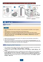
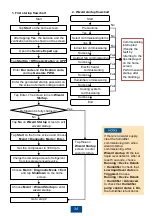
1. On the home page, tap
Shutdown.
2. Turn off the main switch of indoor unit and outdoor unit.
3. (Optional) If the smart cooling product needs to be maintained in power-off mode or long-term
power-off, switch off the smart cooling product circuit breaker on PDC.
12
(Optional) Power-off
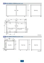
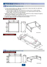
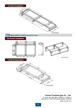
Appendix 1: Base Dimensions
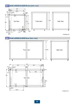
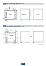
1. You are advised to make the base using angle irons, square irons, or channel steel, with a
width of 50 mm and thickness of 4
–5 mm.
2. The dotted lines in the figure show the area for fan lowering and bottom pipe and cable routes.
Avoid this area when preparing the base. Here the angle iron preparation is used as an
example:
• If the angle iron is 50 mm wide, the base will block the holes for routing water inlet and outlet
pipes. You need to cut holes on the channel steel to avoid the blockage.
• If the angle iron is 72.5 mm wide or wider, the base will block the path for lowering the fan
and holes for routing cables and water inlet and outlet pipes. You need to cut holes on the
channel steel to avoid the blockage.
• If the angle iron is wider than 50 mm and narrower than 72.5 mm, the base will block the
path for routing cables and water inlet and outlet pipes. You need to cut holes on the
channel steel to avoid the blockage.
3. The holes for bolts securing base and cabinet are 37.5 mm and 50 mm away from the sides. If
you cannot directly drill holes on the base for welding nuts, weld the nuts onto L-shaped
components or components with other shapes, and then secure the components to the base.
4. Attach shock absorption bars (EPDM rubber, 5 mm thick) to the base top.
5. Control the welding errors during the welding; otherwise, the base may be unusable.
Ambient
Temperature
Proper Discharge Pressure
Range (Running > Device
Details > Compressor)
Proper Suction Pressure
Range (Running > Device
Details > Compressor)
Proper Overheating
Degree (Running >
Device Details > EEV)
< 15
°
C
1.5
–2.5 MPa
0.7
–1.2 MPa
8
–15
°
C
15
–35
°
C
1.5
–3.1 MPa
35
–45
°
C
2.5
–3.8 MPa
> 45
°
C
3.1
–4.15 MPa
When the compressor is 3000 rpm, the following table lists the proper system values.

